


User’s Manual
21
3. Cable Connections
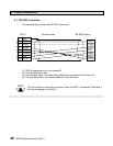
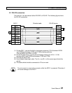
3.2 RS-422 connection
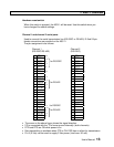
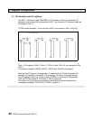
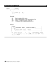
The channel 1 can be selected either RS-232C or RS-422. The following figure shows
the RS-422 connection.
AS311 Shielded cable RS-422 device
(1) On the AS311, connect the built-in terminating resistors (120 Ω) between RXDA
and RXDB and between CTSA and CTSB by setting switches.
(Set the SW3-2 and SW3-3 to ON)
(2) On the RS-422 device, connect the terminating resistors R (120 Ω - 1/2 W)
between RXDA and RXDB and between CTSA and CTSB.
(3) Connect SG each other.
(4) Use shielded twisted-pair cable. The A (+) and B (-) of the same signal should be
paired.
(5) The cable shield should be connected to FG at one end.
Do not connect or remove the connector while the AS311 is powered. Otherwise, it
will cause damage to the AS311.
FG
RXDA
RXDB
TXDA
TXDB
SG
CTSA
CTSB
RTSA
RTSB
1
10
21
11
22
7
12
23
13
24
FG
TXDA
TXDB
RXDA
RXDB
SG
RTSA
RTSB
CTSA
CTSB
R
R
NOTE