


User’s Manual
33
4. Register Configuration
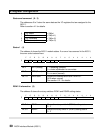
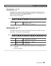
CH1 transmit error (17) and
CH2 transmit error (81)
The address 17 (for channel 1) and the address 81 (for channel 2) indicate the error
contents if an error has occurred during message transmitting. This information is set
during the write sequence for message transmitting.
Refer to section 6.2.4 for details.
F E D C B A 9 8 7 6 5 4 3 2 1 0
17 or 81
0 0 0 0 0 0 0 0 Transmit error code
Bit 7-0 Transmit error
code
Shows the error code for transmitting.
(H00 when normal)
See section 6.2.4 for details.
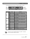
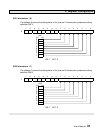
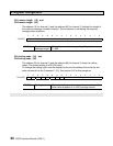
CH1 channel status (18) and
CH2 channel status (82)
The address 18 (for channel 1) and the address 82 (for channel 2) indicate the control
signal status. This information is always updated.
F E D C B A 9 8 7 6 5 4 3 2 1 0
18 or 82
0 0 0 0 0 0 0 IDL DSR 0 0 0 CTS 1 0 0
Bit 8 IDL (Idle) 1 = transmitter is idle state
0 = transmitter is non-idle state
Bit 7 DSR
(Data set ready)
1 = DSR is ON
0 = DSR is OFF Note (1)
Bit 3 CTS
(Clear to send)
1 = CTS is ON
0 = CTS is OFF
Note: (1) The channel 1 does not support DSR. Therefore, bit 7 of the address 18 is
always 0.
(2) The bit 2 is always 1.