


30
ASCII Interface Module (AS311)
4. Register Configuration
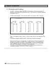
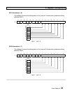
Status and command (0 - 3)
The addresses 0 to 3 store the same data as the I/O registers that are assigned to the
AS311.
Refer to section 4.1 for details.
0 CH1 status = XW(n)
1 CH2 status = XW(n+1)
2 CH1 command = YW(n+2)
3 CH2 command = YW(n+3)
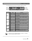
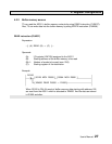
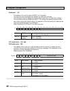
Status 1 (4)
The address 4 shows the AS311 module status. If an error has occurred in the AS311,
the error code is stored here.
F E D C B A 9 8 7 6 5 4 3 2 1 0
4
RDY ERR 0 0 0 0 0 0 Error code
Bit F RDY (Ready) 1 = operating normally
0 = under initialization or error state
Bit E ERR (Error) 1 = error state
0 = no error (normal)
Bit 7-0 Error code Shows the detected error item if ERR is 1.
(H00 when normal)
See section 6.2.1 for details.
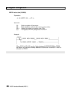
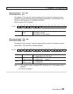
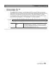
RSW1/2 information (5)
The address 5 stores the rotary switches RSW1 and RSW2 setting status.
F E D C B A 9 8 7 6 5 4 3 2 1 0
5
0 0 0 0 0 0 0 0 RSW1 RSW2
Bit 7-4 RSW1 Stores the rotary switch 1 (RSW1) setting status.
0 - F
Bit 3-0 RSW2 Stores the rotary switch 2 (RSW2) setting status.
0 - F