


3. ELECTRONICS
EO18-33013
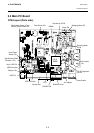
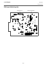
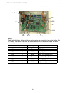
3.3 Main PC Board
3- 5
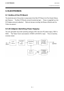
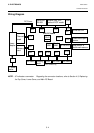
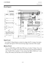
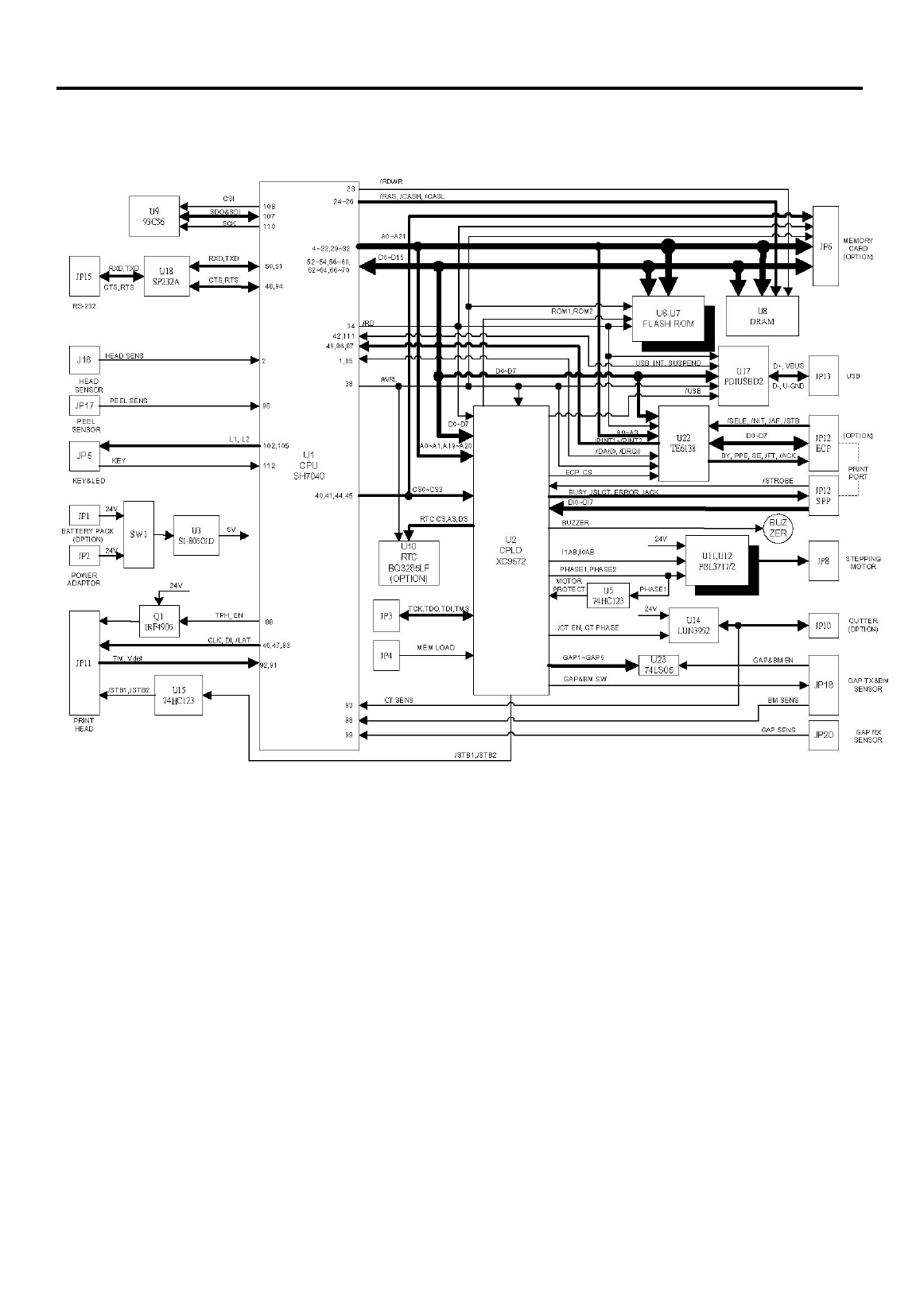
Block Diagram
Reset Circuit
The S-80845 IC Voltage Detector can detect the voltage while RC is charging. And outputs
the system reset signal of “LOW” when the driving voltage is lower than 4.5Vdc (Typical).
Memory Circuit
There are 2MB DRAM and 2MB Flash ROM built on the Main PC Board. This is the
memory circuit. The U6&U7 type 1M Byte Flash ROM and U8 type 2M Byte DRAM are
used. The MCU R/W pin becomes “H” when reading Flash ROM or DRAM, and “L” when
writing. JP6 is memory card connector, and it can expand to 8MB.