


4. REPLACING THE IMPORTANT PARTS
EO18-33013
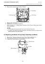
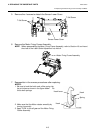
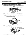
4.3 Replacing the Top Cover, Lower Cover, and Main PC Board
4-5
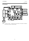
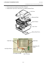
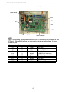
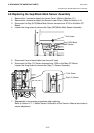
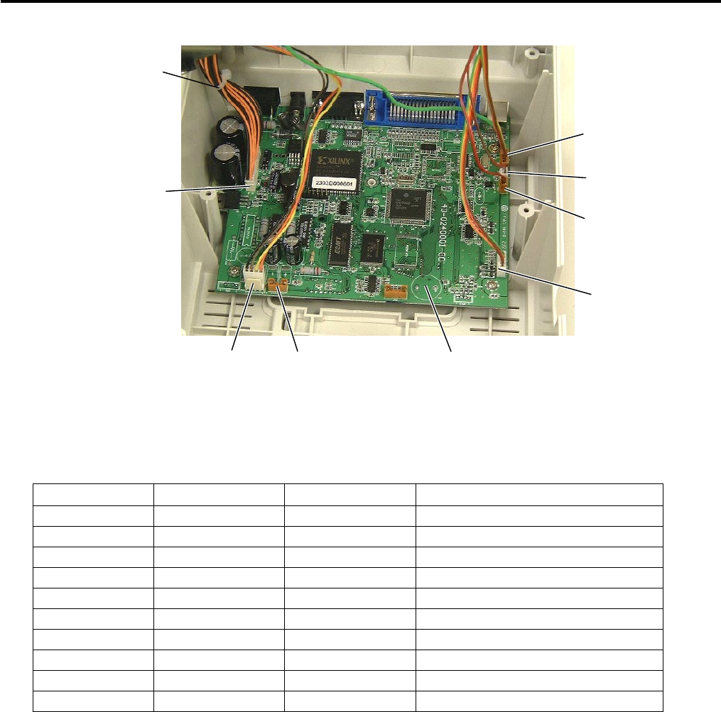
NOTE:
Refer to the following table and above picture when re-connecting the cables to the Main
PC Board. Be careful that there are some cables whose connectors have the same
number of pins.
Connector No. Number of pins Housing color Connected to
JP3 6 Black (Not used.)
JP5 5 Brown LED & Button
JP6 50 Black Memory PC Board
JP8 4 White Stepping Motor
JP10 4 Brown Cutter (GC10 model only)
JP11 26 White Print Head
J16 2 Brown Case/Head Open Switch
JP17 5 Brown (Not used.)
JP18 5 White Gap (LED)/Black mark sensor
JP20 2 White Gap sensor (Tr)
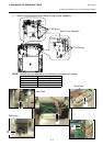
JP11
JP8 JP10
JP5
JP20
J16
JP18
Main PC Board
Cable Band