


4. REPLACING THE IMPORTANT PARTS
EO18-33013
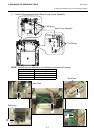
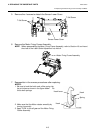
4.4 Replacing the Motor Fixing Frame Assembly and Motor
4-6
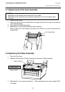
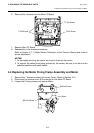
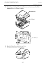
6. Remove the 4 screws from the Main PC Board.
7. Replace Main PC Board.
8. Reassemble in the reverse procedures.
Refer to Section 2.7.1, Media Sensor Calibration of the Owner’s Manual and make a
sensor adjustment.
NOTES:
1. As the cables are long, be careful not to pinch them by the covers.
2. To prevent the cables from being pinched by the covers, be sure to fix them to the
specified positions with cable bands.
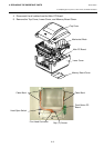
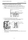
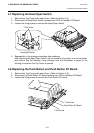
4.4 Replacing the Motor Fixing Frame Assembly and Motor
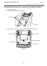
1. Remove the 7 screws to detach the Lower Cover. (Refer to Section 4.3.)
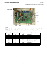
2. Disconnect the harness from JP8 connector on the Main PC Board.
3. Loosen the 2 fixing screws and remove Motor.
T-3x6 Screw
T-3x6 Screw
TT-3x8 Screw
SM-3x6 Screw
SM-3x6 Screw
Motor