


User’s Manual 2-5
The Grand Tour
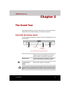
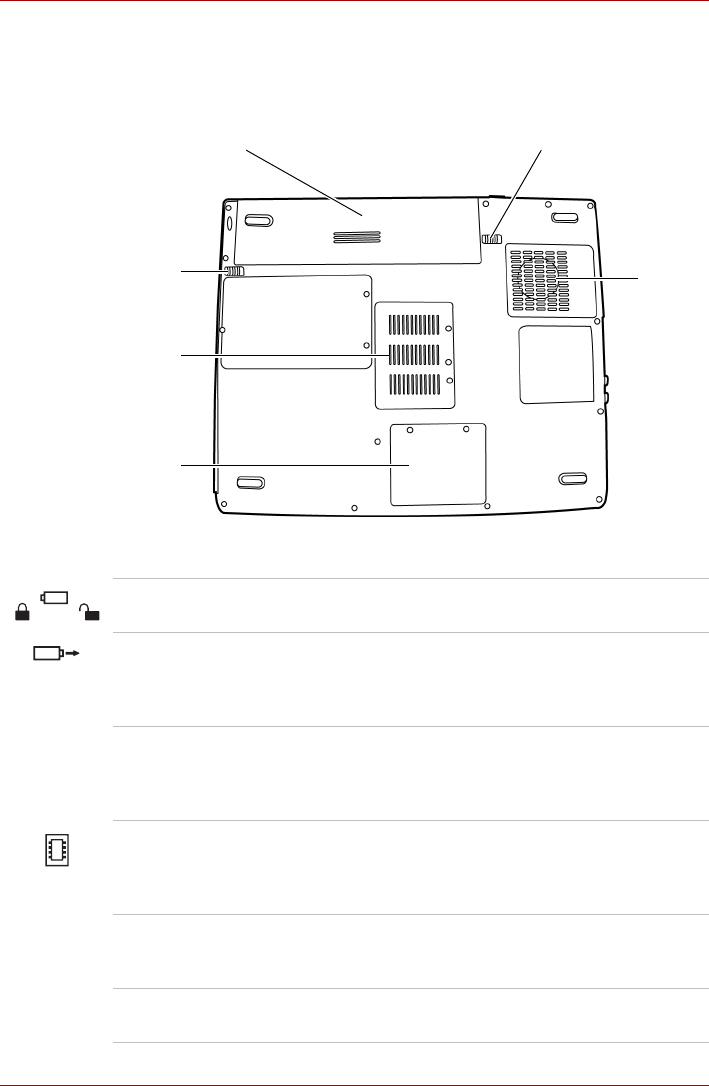
Underside
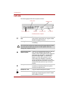
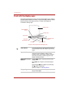
The following figure shows the underside of the computer. Make sure the
display is closed before turning over your computer.
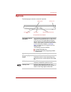
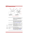
The underside of the computer
Battery Pack Battery Release Latch (2)
Cooling
Vents
Battery
Release
Lock (1)
Memory
Module
Cover
Wireless
LAN
Cover
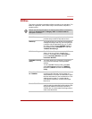
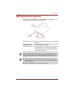
Battery Release
Lock (1)
Slide this lock to prepare the battery pack for
removal.
Battery Release
Latch (2)
Slide and hold this latch to release the battery
pack for removal. For detailed information on
removing the battery packs, refer to Chapter 6,
Power and Power-Up Modes.
Battery Pack The battery pack powers the computer when the
AC adaptor is not connected. For detailed
information on the battery pack, refer to
Chapter 6, Power and Power-Up Modes.
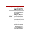
Memory Module
Cover
This cover protects two memory module socket --
one module is preinstalled. Refer to the Memory
expansion section in Chapter 7, Optional
Devices.
Wireless LAN Cover This cover protects the Wireless LAN bay and, if
installed, the Wireless LAN card. (Not all models
support this feature.)
Cooling Vents Cooling vents help prevent the CPU from
overheating.