–3–
M-2299 Application Guide
2.2 Installation of the M-2001
Series Digital Tapchanger
Control
Mount the M-2001 Tapchanger Control to the back
of the M-2299 Adapter Panel and secure with the
four screws provided. The four screws are shipped
in a drawstring bag which is attached to the adapter
panel.
2.3 Installation of the M-2299
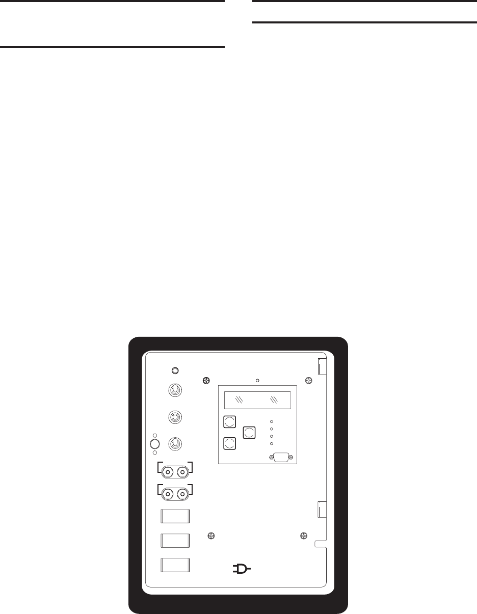
Refer to Figure 2, below.
1. Mount the supplied printed circuit board
against the rear of the cabinet in the
screw holes from the "AUTO/MANUAL,
RAISE/LOWER switch" bracket, utilizing
saved screws. See Figure 4, Wiring
Harness and External Connections.
2. Connect the supplied printed circuit board
TB1 wiring harness to the BT1 terminal
block and capacitor. Refer to Figure 4
for wiring connections.
3. Mount the M-2299 Adapter Panel (with
the M-2001) onto the hinges in the control
cabinet and install the two hinge pins
saved from the original regulator. Leave
the panel swung outward so that the
back of the panel is accessible.
4. Connect the M-2299 and M-2001B wiring
connectors to the supplied circuit board
and Neutral Light. Refer to Figure 4 for
wiring connections.
5. Swing the adapter panel closed and turn
knob to latch securely.
CO. INC
ELECTRIC
BECKWITH
TEST TERMINAL
3 AMP
VOLTAGE
.25 AMP
MOTOR POWER
6 AMP
VOLTAGE IN
METER OUT
AUTO
MANUAL
LOWER
RAISE
INT
EXT
VOLTAGE
SOURCE
M-2299
.
NEUTRAL
LIGHT
TAPCHANGER CONTROL
OFF
OFF
OFF
B
D
-M
DOWN
0120
UP
U
ENTER
E
COM 2
OK
R
O
E
R
L
VPW
EWR
A
REIS
Figure 2 M-2299 Adapter Panel and M-2001 Tapchanger Control in Cabinet


