


–11–
M-2299 Application Guide
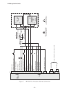
5.1 Bench Test
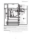
NOTE: This test assumes that the M-2001
Tapchanger Control is connected to the M-2299
Adapter Panel.
1. Apply 120.0 V ac from power source.
2. The display of the M-2001 will
automatically advance to Local Voltage
screen.
3. Increase voltage to 121.2; LOWER LED
should light.
4. Decrease voltage to 118.8; RAISE LED
should light.
5. Set input voltage to 120.0 V ac. Wait
for RAISE and LOWER LEDs to
extinguish.
6. Increase voltage to 122.0 V ac.
7. Start timing when voltage passes
121.0 V.
8. Stop timing when lamp connected to
LOWER output lights (should be 5
seconds).
Resistance
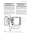
1. Apply 100.0 mA in-phase current to
TB1-14 (load current-polarity) and
TB1-15 (load current-return) of the
adapter panel. (Set S
1
to LDC and S
2
to
I
R
.)
2. Set LDC Resistance to 24.0 V; RAISE
LED should light.
3. Increase input voltage to 132.0 V ac;
RAISE and LOWER LEDs should be
extinguished.
4. Set LDC Resistance to –24.0 V; LOWER
LED should light.
5. Decrease input voltage to 108.0 V ac;
both RAISE and LOWER LEDs should
extinguish.
6. Set LDC Resistance to 0.0 V.
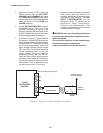
Voltage Source Switch
1. Set AUTO/OFF/MANUAL switch to OFF.
2. Set VOLTAGE SOURCE switch to EXT.
3. Verify no manual Raise or Lower output.
4. Attach voltmeter to Meter Out terminals.
5. Verify no voltage is present.
6. Apply 120 V ac to the Voltage In jack
(Black-Neutral, Red-Hot).
7. Set AUTO/OFF/MANUAL switch to
AUTO.
8. Verify normal raise and lower operation.
9. Return the VOLTAGE SOURCE switch
to INT.
Counter/Neutral Light
1. Set the M-2001 Tapchanger Control to
display the Operations Count screen.
2. Verify counter operation by connecting
a switch between TB1-13 (operations
counter input) and TB1-8 (neutral) of the
adapter panel.
3. Jumper TB1-11 (neutral light) to TB1-8
(neutral).
4. The neutral light on the adapter panel
should light.
5. Remove the jumper.
Block Raise/Block Lower/Dead Band
1. Set Block Raise to 126.0 V.
2. Set Block Lower to 114.0 V.
3. Set the M-2001 Tapchanger Control to
display the Bias Voltage screen.
4. Press ENTER.
5. Increase voltage to 126.5 V; BR should
appear on the screen.
6. Increase voltage to 128.5 V; BR goes
off and FL appears on the screen.
7. Decrease voltage to 113.5 V; BL appears
on the screen.
—Bench Test Complete—