


–12–
M-2299 Application Guide
1
2
3
4
5
6
7
8
9
10
11
12
13
14
15
27
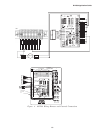
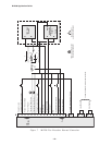
Contact Wetting Supply (+12 V dc)
Voltage Reduction Step #2 Input
Tapchanger Raise Output
Tapchanger Lower Output
Voltage Reduction Step #1 Input
Neutral
Motor Power
Regulated Voltage
Neutral Light
Operations Counter Input
Load Current (Polarity)
Load Current (Return)
H
N
H
N
120 V Fixed
Supply
Adjustable
80 to 140 V ac
Supply
H
TB2
TB1
OFF
LDC
R1
C1
S1
S2
Discrete Elements or Doble F2200
(approx. 1200 ý, 15 W or greater)
(approx. 2.2 µF, 600 V ac Mylar Film)
Variac
Input
I
Tap
Position
I
Load
120 V Lamp or Relay Coil
for Functional Indicator
Normally open
pushbutton test switch
16
17
18
19
Local/Remote
Auto Disable
Jumpers in place for motor power continuity.
I
R
I
L
N/U
Polarity Contact
Resistor Network Wiper
Position Resistor
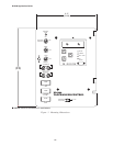
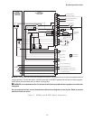
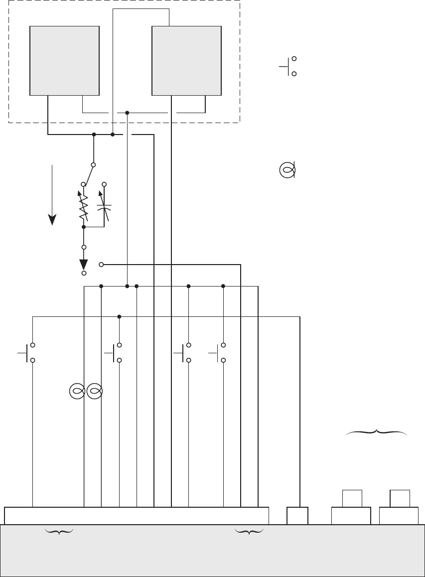
Figure 7 M-2299 Test Procedure External Connection