


–13–
M-2299 Application Guide
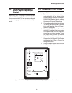
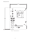
5.2 M-2001 Checkout Procedure
NOTE: This test of the M-2001 assumes that the
unit remains connected to the adapter panel.
Basic Operational Test
1. Apply 120.0 V ac to TB1-9 (motor power)
and TB1-10 regulated voltage) of adapter
panel.
2. Connect neutral to TB1-8 (neutral).
3. Verify local voltage y input voltage
±0.3 V.
4. Apply 100.0 mA in-phase current to
TB1-14 (load current-polarity) and
TB1-15 (load current-return) of the
adapter panel. Verify Control Load I y
100 mA and Power Factor y 1.0 ±0.02.
5. Verify UP, DOWN and ENTER buttons
work.
—Checkout Procedure Complete—
5.3 In-Service Test
1. Set the M-2001 Tapchanger Control to
display Bias Voltage screen.
2. Press ENTER.
3. Use UP and DOWN buttons to cause
RAISE and LOWER outputs.
—In-Service Test Complete—
Return unit to desired settings
6.0 Checkout Procedure
NOTE: All Beckwith Electric units are fully cali-
brated at the factory. There is no need to re-calibrate
the units before initial installation.
Set the AUTO/OFF/MANUAL switch to OFF.
Inspect the MOTOR POWER and VOLTAGE fuses
to ensure they are correctly sized and have not
blown.
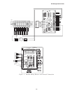
6.1 Power
1. Remove any external connection
between TB1-9 and TB1-10 which are
located on the adapter panel printed
circuit board. Also remove any voltage
applied to TB1-9 externally. Using a
voltmeter, make sure that the voltage
applied to TB1-10 is nominal 120 V ac
with respect to TB1-8 (neutral). Apply
power to TB1-10 (hot) and TB1-8
(neutral).
8 WARNING: Voltage applied at the
METER OUT
test terminal may energize the regulator or trans-
former to a high voltage through the voltage
transformer.
Death or severe electrical shock can occur.
Do not connect any voltage source at the
METER
OUT
test terminal.
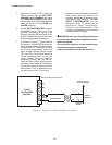
2. Connect a voltmeter to the METER OUT
test terminal on the front of the adapter
panel. 120 V ac should be indicated.
▲ CAUTION: Do not reverse the ground and hot
wires when connecting an external source. A 3 AG
fuse (F2) is installed to protect the relay from dam-
age if these connections are accidentally reversed.
Spare fuses are supplied inside the fuse holders.
Units returned with only a blown fuse are not cov-
ered by warranty, and a nominal repair charge will be
made for replacement of the fuse. Please check the
fuse before returning the unit for repair, in order to
avoid unnecessary repair charges.