


–9–
M-2299 Application Guide
*
*
TB1-11
TB1-12
TB1-6
TB1-10
TB1-7
TB1-9
MOTOR
SUPPLY
TAPCHANGER
CONTROL
M-0329
90 BACKUP
LOWER
BLK
RAISE
BLK
LOWER
84L
84R
120 VAC POWER
3
2
4
14
15
REGULATED VOLTAGE
ALARM
LIMIT SWITCHER, AUXILIARY CONTACTS AS
REQUIRED IN MOTOR CONTROL CIRCUITS
84R - RAISE MOTOR AUXILIARY RELAY
84L - LOWER MOTOR AUXILIARY RELAY
1
TB1-9
TB1-7
TB1-8
R
L
*
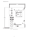
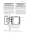
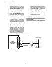
NOTE: If first customer protection is not required, delete these connections.
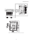
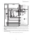
Figure 6 Tapchanger Control and LTC Backup Control Interconnections
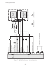
3.2 Typical Connections for
Toshiba Regulators
In general, the tapchanger motor must be operated
from a different transformer than the VT used to
measure regulated voltage. If this is not done,
hunting at the upper band edge may result. As soon
as the motor starts and before it is sealed in, the
motor current can drop the voltage within the band
and reset the control. Some motor seal-in schemes
are fast enough to prevent this, but others are not.
A typical connection for an M-2299 is shown in
Figure 5, M-2001 and M-2299 Typical Connections.
Connections are simplified and may not show all
functions required in a typical load tapchanging
transformer control scheme; for example, seal-in
contacts, limit switches, etc.
3.3 Use of the M-0329 LTC
Backup Control with the
Tapchanger Control
The M-0329 is a single-phase, solid-state backup
control that prevents a defective tapchanger control
from running the voltage outside the upper and
lower voltage limits. The Block Raise and Block
Lower voltage levels are set by accurately calibrated
dials.
The M-0329 LTC Backup Control is connected as a
two terminal device to the voltage transformer.
Figure 6, below, shows the typical interconnection
of the two devices with motor auxiliary relays.
The M-0329 Instruction Book is available on request
and gives added details. Please refer to the M-0329
Instruction Book for complete ordering information.