


–1–
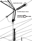
M-2299 Application Guide
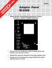
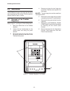
The Beckwith Electric M-2299 Adapter Panel, used
in conjunction with the M-2001 Series Digital
Tapchanger Control, uses modern electronic digital
design and digital processing circuitry to achieve
an overall stability and resolution unattainable with
electromechanical and analog design tapchanger
controls. CMOS semiconductors are used throughout
the design.
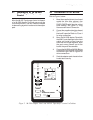
NOTE: The hinge pins
must be saved
from the
original control. The BT terminal blocks remain in
the control cabinet.
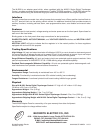
1.0 Description
Standard Features
The M-2299 Adapter Panel, with the M-2001 Series
Digital Tapchanger Control, provides a solid-state
voltage control relay designed to directly replace
the Toshiba TB-R800 control. The combination of
the Tapchanger Control and Adapter Panel includes
the following features:
1. Voltage waveform sampling and digital
processing circuitry ensure accurate rms
voltage sensing in the presence of
distortion on the input voltage and
current.
2. Accuracy exceeds the ANSI/IEEE
C57.15-1986 Class 1 specification over
the temperature range of –40° C to
+70° C.
3. Input and output circuits are protected
against system transients. Units pass
all requirements of ANSI/IEEE C37.90.1-
1989, which defines surge withstand
capability. All input and output terminals
will withstand 1500 V ac rms to chassis
or instrument ground for one minute with
a leakage current not to exceed 25 mA,
from all terminals to ground. Input and
output circuits are electrically isolated
from each other, from other circuits and
from ground.
4. Separate motor power, test terminal and
voltage sensing fuses are easily
changed from the front panel and spare
fuses are provided in their respective
fuseholders.
5. Easily tested by use of the following:
a. VOLTAGE SOURCE switch
disconnects the voltage transformer
input and connects the VOLTAGE
IN binding posts to the voltage input
and motor circuit.
b. VOLTAGE IN binding posts on the
front panel allow application of a
120 V rms nominal voltage to the
unit for test procedures.
c. METER OUT binding posts on the
front panel allow reading of the input
voltage when used in conjunction
with the BIAS TEST VOLTAGE
screen of the M-2001 Series Digital
Tapchanger Control.
d. RAISE and LOWER band edge LEDs
on the M-2001 Tapchanger Control
indicate when the input voltage is
outside the voltage band.
6. NEUTRAL light illuminates when the
regulator is in the neutral tap position.
7. AUTO/OFF/MANUAL switch allows
manual operation of the control.