


–14–
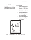
M-2299 Application Guide
M-2299
TAPCHANGER
CONTROL
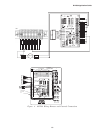
TB1 on printed circuit board
14
15
LOAD CURRENT
AUX
CT
A
5 A
200 mA
3
4
LDC-CT
XXXX:5 A
Shorting
device
Normally 1-CT on
X , X , X bushing
123
N/U
N/U
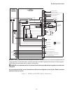
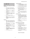
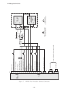
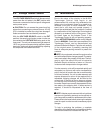
Figure 8 Setup for Current Checkout Procedure
3. Apply motor power to TB1-9 (hot) and
TB1-8 (neutral). Set the AUTO/OFF/
MANUAL switch to MANUAL and using
the RAISE/OFF/LOWER switch, verify
that the motor runs in the proper direction
when this switch is in the RAISE and
LOWER positions.
4. Set the AUTO/OFF/MANUAL switch to
the AUTO position. Refer to the Field
Checkout Procedure as found in the
Status & Setpoint Review Guide of the
M-2001 Tapchanger Control Instruction
Book for test/operation procedures.
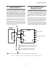
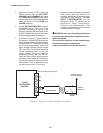
5. As shown in Figure 6-1, Typical External
Connections, in the M-2001B Instruction
Book, temporarily place a shorting device
across the LDC-CT secondary to short
the line drop compensator circuit, and
place another shorting device across
TB1-3 and TB1-4 to short the circulating
current paralleling input, for the load
current check. Insert an ammeter
between the polarity input and TB1-14.
Open the load current shorting device
and with a known load on the transformer
or regulator, measure the current in the
load current circuit to ensure that this
current is correct for 0.2 A full load.
6. Replace the shorting device across the
load current input and remove the
ammeter. Reconnect polarity to the unit
and remove both jumpers. The LINE
DROP COMPENSATOR will be
activated. Correct CT polarity can be
checked by simply incorporating
sufficient +R compensation. The
regulator should time out and run so as
to raise the output voltage.
8 WARNING: In no case should the load current
circuit be interrupted with the regulator or trans-
former energized.
Do not remove auxiliary current transformers
without shorting the current inputs.
Death or severe electrical shock can occur.