


–6–
M-2299 Application Guide
2.4 Lightning Protection
It has been determined that transient voltages in
excess of 1500 V ac rms can exist on the “ground”
lead normally tied to TB1-8 on the printed circuit
board. In the Tapchanger Controls, these voltages
are suppressed by varistors which still permit the
unit to pass a 1500 V ac Hi Pot test for one minute
with a leakage current of approximately 15 mA, all
terminals to ground.
▲ CAUTION: For proper protection against system
surges, chassis ground must be connected to earth
ground.
Multiple VT grounds far apart must be avoided
since a varying difference in ground voltage could
add or subtract from the effective voltage and
cause variation in the Tapchanger Control’s
bandcenter voltage setpoint.
3.0 External Connections
Power and voltage sensing are obtained either from
a common source or from independent sources
having a nominal 120 V ac output. Normally, this is
line-to-neutral voltage, although line-to-line voltage
can also be used if recognition is made of any
phase shift between the voltage and current signals
when using line drop compensation.
Load current must be reduced by an appropriate
auxiliary current transformer to 0.2 A “full scale”
before connecting to the M-2299 current inputs.
The Beckwith Electric M-0121 (5.0 A to 0.2 A) or
M-0169 (5.0 A or 8.66 A to 0.2 A) Auxiliary Current
Transformer can be used for this purpose. The
M-0121 can be used with Beckwith Electric
Tapchanger Controls when the only burden present
is the Line Drop Compensator circuit of the voltage
regulating relay. The M-0169 is used in high burden
circuits, such as are found in paralleling schemes.
Outputs of the auxiliary CTs are protected against
overvoltage. For further information, obtain Beckwith
Electric Application Note #17, “Basic Considerations
for the Application of LTC Transformers and
Associated Controls.”
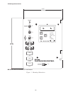
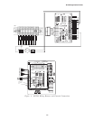
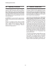
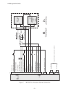
The external connections for the M-2299 are made
to terminal blocks TB1 and TB2 on the printed
circuit board. The wiring harness and external
connections for the M-2299 are shown in Figure 4,
Wiring Harness and External Connections, and
Figure 5, M-2001 and M-2299 Typical Connections.