


E6581343
- 10 -
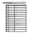
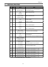
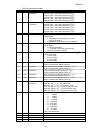
3.3. ZSW Status Word Data
Bit Valur Name Note
1
Ready to switch-on Control word bit 0 = 0 and bit1, 2, 10 are set to 1.
0
0
Not ready switch-on
Control word bit 0 = 0, 1, 2 or 10 are set to 0,
or the inverter is tri
pp
ed.
1
Ready Refer to control word, bit 0.
1
0
Not ready -
1
Operating enabled Refer to control word, bit 3.
2
0
Operation inhibited -
1
Fault Inverter is faulted.
3
0
Fault-free Inverter is not tripped.
1
No OFF 2 -
4
0
OFF 2 "OFF 2" command present
1
No OFF 3 -
5
0
OFF 3 "OFF 3" command present
1
Switch-on inhibit
Control word bit1 or 2 is set to 0
or fault trip has been acknowledged.
6
0
No switch-on inhibit -
1
Alarm
Drive still operational: Alarm in service parameter: No
acknowledgement.
7
0
No alarm Alarm not present or alarm has disappeared again
1
Setpoint / actual value
monitorin
g
in the tolerance
-
8
0
As above, but not
in the tolerance range
-
1
Control request
Run command or frequency setting is valid
via Profibus.
9
0
Local operation Control only possible on the VF-AS1/PS1.
1
f or n reached
Actual value = comparison value (at reference),
set via the parameter number
10
0
f or n fallen below -
11 ----
Device-specification
OUT1 terminal monitor
OUT1 output terminal monitor
(bit 0 of fd07. Function selection: f130)
12 ----
Device-specification
OUT2 terminal monitor
OUT2 output terminal monitor
(bit 1 of fd07. Function selection: f131)
13 ----
Device-specification
FL terminal monitor
FL output terminal monitor
(bit 2 of fd07. Function selection: f132)
14 ----
Device-specification
OUT3 terminal monitor
OUT3 output terminal monitor
(bit 3 of fd07. Function selection: f133)
15 ----
Device-specification
OUT4 terminal monitor
OUT4 output terminal monitor
(bit 3 of fd07. Function selection: f134)
*Bit 11 - 15 are the ON/OFF status monitor of each terminals.