


E6581343
- 1 -
Contents
1. Introduction...............................................................................................................................................2
2. Connection Information ............................................................................................................................3
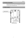
2.1. Exterior features...........................................................................................................................3
2.2. PDP002Z Device Data.................................................................................................................4
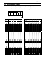
2.3. Setting a station address .............................................................................................................5
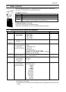
2.4. Status indicator ............................................................................................................................7
2.5. Communications-related parameters...........................................................................................7
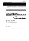
3. “PROFIdrive” Profile .................................................................................................................................8
3.1. PPO TYPE ...................................................................................................................................8
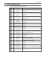
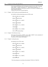
3.2. STW Control Word Data ..............................................................................................................9
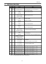
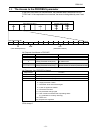
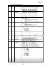
3.3. ZSW Status Word Data..............................................................................................................10
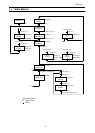
3.4. State Macine ..............................................................................................................................11
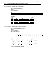
3.4.1. Examples of driving by the State Machine.........................................................................12
3.5. The Access to the PROFIBUS parameter .................................................................................13
3.5.1. Examples of reading or changing the PROFIdrive parameter...........................................15
3.6. Access to the VF-AS1/PS1 parameter ......................................................................................17
3.6.1. Examples of reading or changing the VF-AS1/PS1 parameter .........................................17
4. ”USER DEFIND” Profile .........................................................................................................................19
4.1. How to use .................................................................................................................................20
4.2. The overview of the VF-AS1/PS1 parameter.............................................................................21
4.2.1. FA06 (Command word 1 from internal option PCB) ..........................................................21
4.2.2. FA23 (Command word 2 from internal option PCB) ..........................................................21
4.2.3. FA07 (Frequency reference from internal option PCB) .....................................................22
4.2.4. FA33 (Torque reference from internal option PCB) ...........................................................22
4.2.5. FA50 (Terminal output data from comm.) ..........................................................................22
4.2.6. FA51 (Analog output (FM) data from comm.) ....................................................................22
4.2.7. FA52 (Analog output (AM) data from comm.) ....................................................................22
4.2.8. FD01 (Inverter status (real time)).......................................................................................23
4.2.9. FD00 (Output frequency (real time)) ..................................................................................23
4.2.10. FD03 (Output current (real time)).......................................................................................23
4.2.11. FE36 (Analog input value VI/II) ..........................................................................................24
4.2.12. FE37 (RX Input) .................................................................................................................24
4.2.13. FE60 - FE63 (My Monitor)..................................................................................................24
4.2.14. FE14 (Cumulative run time) ...............................................................................................24
4.2.15. FE40 (Analog output (FM)) ................................................................................................24
4.2.16. FC91 (Alarm code).............................................................................................................25
4.2.17. FD06 (Input TB Status) ......................................................................................................25
4.2.18. FD07 (Output TB Status) ...................................................................................................25
4.2.19. FC90, FE10 - FE13 (Inverter fault).....................................................................................26
4.3. About GSD file ...........................................................................................................................27
- 1/27 -