


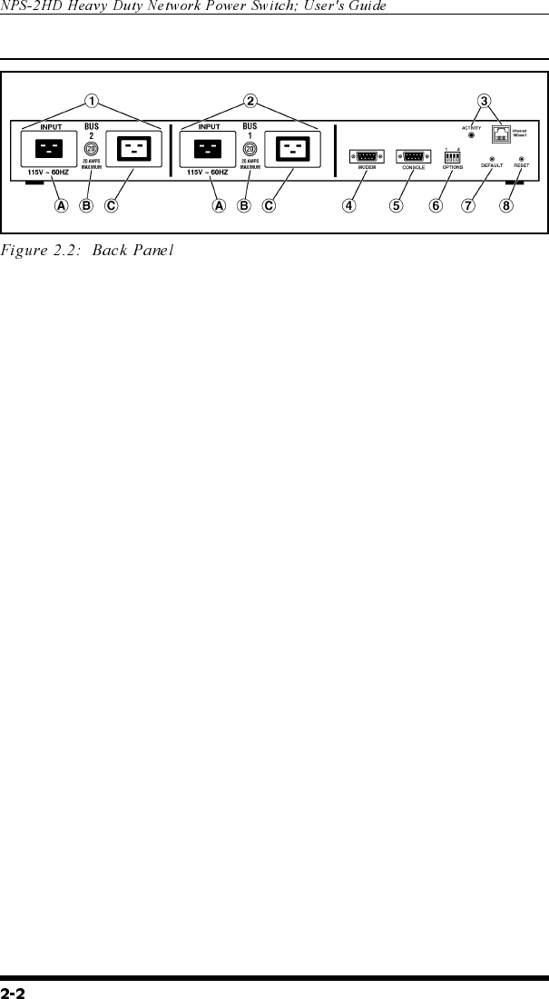
2.2. Back Panel
À
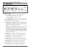
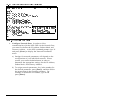
Bus 2 (Plug 2): Includes the following components:
A) Power Inlet: Supplies power for Bus 2.
B) Circuit Breaker: 115 VAC, 20 Amps
C) Switched Outlet: Each bus can switch up to 20 Amps.
Á
Bus 1 (Plug 1): Same as Item 1 above, except the Bus 1
Power Inlet supplies power to Bus 1.
Â
Network Port and Activity Indicator: A 10BaseT, RJ45
Ethernet port for connection to your TCP/IP network. To
communicate via Network, you must first specify network
parameters as described in Section 5.6.
Note: The NPS-2HD features a 10BaseT interface. When
connecting the NPS to a 100BaseT interface, note that
most 100BaseT router switches will autosense to determine
if the device is 100BaseT or 10BaseT and then configure
the network interface accordingly. If your router switch
does not autosense, then the network interface port must be
manually set to 10BaseT.
Ã
Modem Port: A Male RS-232, DB9 Connector, DTE
configuration. For connection to an external modem.
Ä
Console Port: A Male RS-232, DB9 Connector, DTE
configuration. For connection to a local PC.
Å
Option Switches: A bank of four DIP Switches which
select default settings for the baud rate and other features.
Æ
Default Button: Used in conjunction with the Reset
Button to reset the unit to defaults (see Section 4.3.)
Ç
Reset Button: Used in conjunction with the Default
Button to reset the unit to defaults (see Section 4.3.)