


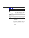

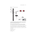

16 CHAPTER 1: INTRODUCING THE ROUTER
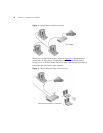
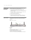
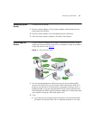
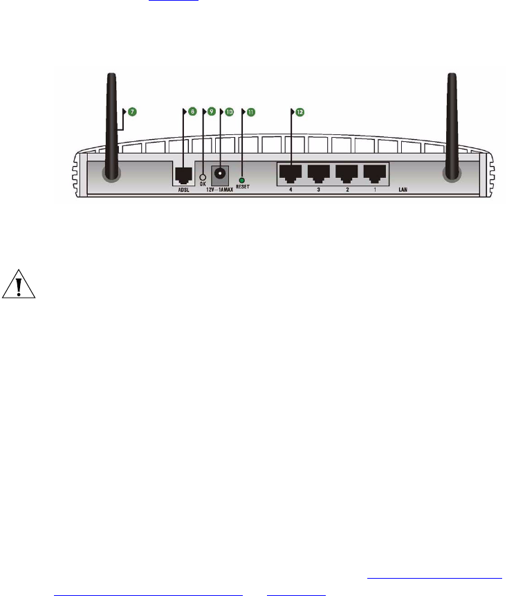
The rear panel (Figure 4) of the Router contains four LAN ports, one ADSL
port, a reset button, a power OK LED, and a power adapter socket.
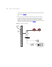
Figure 4 Router - Rear Panel
7 Wireless Antennae
The antennae should be placed in a ‘V’ position when initially installed.
CAUTION: Do not force the antennae beyond their mechanical stops.
Rotating the antennae further may cause damage.
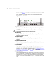
8ADSL Port
Using the RJ-11 cable provided, you should connect your Router to the
telephone socket via a splitter.
9Power OK LED
Indicates the Router is powered on, the power adapter is working
properly.
10 Power Adapter Socket
Only use the power adapter that is supplied with this Router. Do not use
any other adapter.
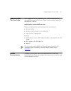
11 Reset Button
If you want to reset your Router to factory default settings, and cannot
access the web management interface (for example, due to a lost
password), then you may use this button. Refer to “
Forgotten Password
and Reset to Factory Defaults” on page 104 for further details.
12 Ethernet Ports
Using suitable RJ-45 cables, you can connect your Router to a computer,
or to any other piece of equipment that has an Ethernet connection (for
example, a hub or a switch). These ports have an automatic MDI/MDIX
feature, which means either straight-through or a crossover cable can be
used.