


Installation Summary
Note: The installation activities described in the following sections should be
undertaken by TRAINED SERVICE PERSONNEL ONLY.
Table 2-1 lists the steps to follow to install the 6412M-25-TP module. Each step is
described in detail in this chapter.
Note: Before installing an 6412M-25-TP module in an ONcore switching hub, make
sure that an ONcore ATM Switch/Control module is installed in slots 9 and 10 (or 11
and 12 in a 17 slot model), and that an ONcore ATM Switch/Control console has
already been configured. If an ONcore ATM Switch/Control module is not installed, the
Reset LED on the 6412M-25-TP module will start blinking when you insert the module.
Table 2-1. Installation Steps
Step Refer to
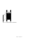
1. Insert the 6412M-25-TP module into a vacant slot:
ONcore: 1 to 8 on 10-slot models (or 1 to 8, 12 to
17 on 17-slot models).
CELLplex 4000: Any vacant slot in the expansion unit.
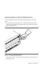
“Installing the Module in
an ONcore Hub” on
page 2-4 (ONcore)
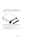
“Installing the Module in a
CELLplex 4000
Expansion Unit” on
page 2-7 (CELLplex
4000)
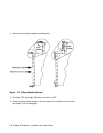
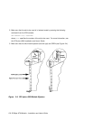
2. Set up connections between the ONcore 12-Port 25
Mbps ATM I/O Module ports and other ATM devices using
the appropriate Twisted Pair (TP) cables and connectors.
“Connecting ATM
Devices” on page 2-10
Chapter 2. Installation 2-3