


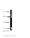

Front Panel
ATM connections are made through the 6412M-25-TP module by means of the ports on
its front panel and its backplane interfaces. The front panel is shown in Figure 3-1 on
page 3-10. The meaning of each LED is shown in Table 3-1.
By pressing the Module Reset button, you interrupt and reset the operation of the
6412M-25-TP module. All ATM data traffic and connections that are being transmitted
are stopped, and the Reset LED lights while the reset is performed. The change in
status of the 6412M-25-TP module (from normal operation to reset status) is reported to
the ATM Control Point.
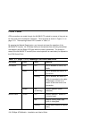
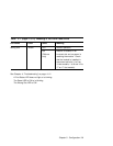
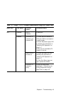
Table 3-1 (Page 1 of 2). Meaning of the Front Panel LEDs
LED Name Color State Meaning
Port Status None OFF Port is disabled or there is no
traffic.
Green ON Port is enabled and there is a
connection.
Blinking Port is enabled, but either no
cable is connected or the cable
is damaged, or there is no
station at the other end of the
connection.
Yellow ON
(or blinking)
Normal operation (traffic
detected).
Module Reset Yellow OFF Normal operation. Module is
not being reset.
ON Module is being reset; data
traffic is interrupted.
Blinking No 6416SW installed or module
faulty.
3-8 25 Mbps ATM Module - Installation and User's Guide