


Configuring Virtual Circuits 137
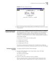
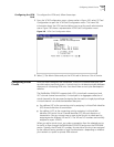
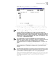
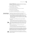
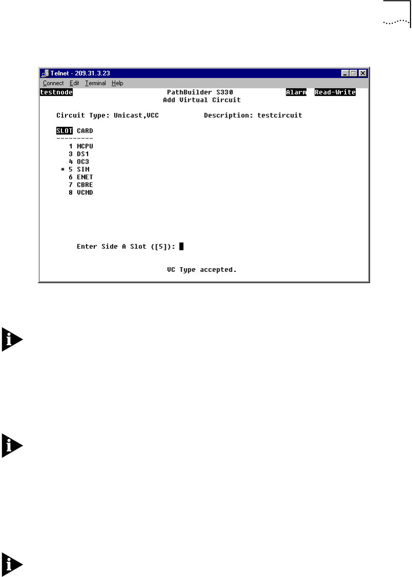
Figure 107 Selecting a Slot for Side A of the Virtual Circuit
3 Enter the slot number for the module that you want to define as side A of the
virtual circuit. For example, to assign the SIM card as side A, you would enter 5.
The default slot number is indicated by an asterisk. To select the default slot
number, simply press [Enter].
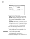
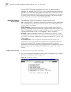
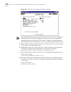
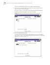
After you enter the slot number, the Add Virtual Circuit screen displays the
selected slot number and port type, lists the parameters you will enter for side A of
the circuit, and prompts you to set the first parameter. The parameters listed vary,
depending on the type of port you selected. See “Virtual Circuit Parameters”, later
in this section, for parameter descriptions.
You can also create an in-band circuit between two nodes by defining the
PathBuilder S330/S310 MCPU—with its own IP address—as one side of the virtual
circuit. This enables you to manage a remote hub from a local network
management station. See “Configuring In-band Management” in Chapter 3, for
details.
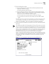
4 Follow the prompts that appear at the bottom of the screen, pressing [Enter] after
each entry. Default values are listed in square brackets ([ ]) at the end of each
prompt.
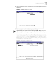
Your settings are added to list of parameters at the top of the screen as you enter
them. You must enter a setting for all the parameters for which you are prompted
in order to add a circuit. Press [Delete] to back up to a previous selection.
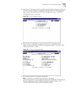
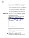
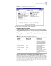
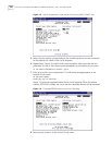
When you have entered a setting for each parameter, the Add Virtual Screen again
displays the list of PathBuilder S330/S310 modules and ports by slot number and
prompts you to enter a slot number for side B of the circuit, as shown in
Figure 108.