


Configuring Virtual Circuits 141
Setting up a PRI PBX Tie Line PRI signaling is a type of CCS in which one
channel (24) is used to signal for the other channels (1-23). This is in contrast to
CAS in which signaling is done on all channels.
To set up a PRI PBX tie line, follow these basic steps:
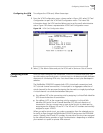
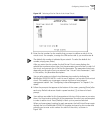
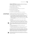
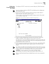
1 Configure the CBR port as follows:
n Set the Port Mode to Structured Data.
n Set the other port parameters as appropriate for your application.
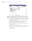
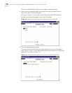
2 Configure the CBR circuits as follows:
n For channel 24, set the Mode to Normal.
n For channels 1-23, set the Mode to DBA.
n Set the other circuit parameters as appropriate for your application.
Defining RS366 (Video)
Virtual Circuit Templates
The RS366 video dial feature uses CBR virtual circuits to support dialed video
conferencing over an ATM network. The feature works as follows:
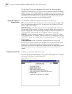
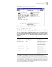
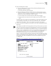
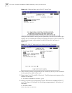
n To set up RS366 virtual circuit templates, you follow the same basic procedure
that you do to add PVC virtual circuits (see “Adding Virtual Circuits” for
details). The RS-366 (video) templates are identified as such when you select
RS366 Template (rather than PVC) as the VC Type (see step 4 under “Adding
Virtual Circuits”). Before you can make a video call, you must set up an RS366
virtual circuit template.
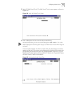
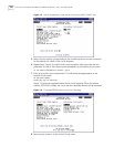
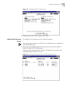
n You can define as many templates as you want to connect to different
destinations.
n When the phone number associated with a given template is dialed, the
PathBuilder S330/S310 software locates the template and uses it to create a
temporary virtual circuit to which it assigns the default description <366 call>.
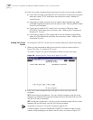
A video connection is established either via the Manual Connect A Site menu, as
described in “Managing Video Dial-up Sessions” ‘later in this chapter, or when
someone dials the phone number associated with the video circuit on a video
keypad.
n Data for the video conference is transmitted and received over the
newly-created <366 call> circuit.
n When the call is disconnected, the system deletes the <366 call> circuit, but
preserves the template upon which the circuit was based for future use.
For further details about video conferencing and information on setting up call
routing tables for point-to-point video conferencing (between remote PathBuilder
S330/S310 switches) and multi-point video conferencing (both between remote
PathBuilder switches and between a central PathBuilder S330/S310 and remote
PathBuilder S330/S310 switches) see “Video Conferencing” in Appendix B.
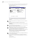
Since only one video virtual circuit is active at any given time, you must build
multiple video-associated virtual circuits—even though they use the same physical
port and T1/E1 channels.