


56 CHAPTER 2: INSTALLATION
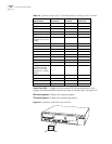
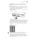
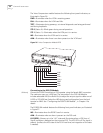
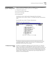
The Voice Compression module features the following front panel indicators, as
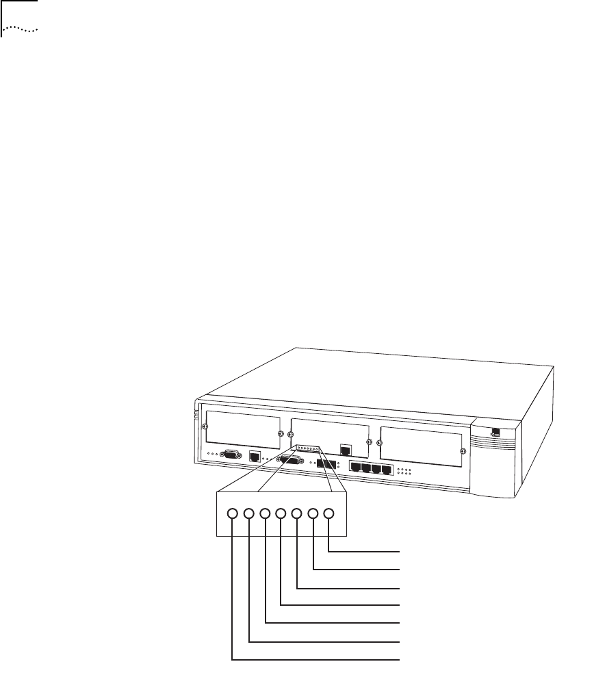
illustrated in Figure 26:
PWR—Illuminates when the VCM is receiving power.
FAIL—Illuminates when the VCM card fails.
TEST—Illuminates during powerup, as internal diagnostics are being performed
and during loopbacks.
STS 0 (Status 0)—Blinks green during normal operation.
STS 1 (Status 1)—Illuminates when the VCM port is in service.
INS—Illuminates when the VCM card is in service.
ALM—Illuminates when there is an alarm present on the VCM card.
Figure 26 Voice Compression Module LEDS
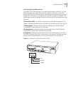
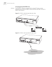
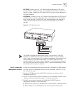
Connecting to the DS3/E3 Module
S330 only Connect the DS3/E3 module to a DS3 repeater using the female BNC connectors.
The maximum coax run is 450 feet. The transmitter in the DS3 UNI Module
includes selectable LBO (Line Build-Out) to adjust the output signal to cable runs of
0-255 or 225-450 feet. Select the LBO during card configuration from the local
terminal or NMS. See “Configuring the DS3/E3 UNI Module”, in Chapter 4 for
details.
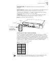
The DS3/E3 UNI module features the following front panel indicators, as illustrated
in Figure 27:
INS—Illuminates when the DS3/E3 card is in service.
ALM—Illuminates when an alarm is present on the DS3 card.
LOS (RED)—Powers up in the “off” state and illuminates when a LOS (Loss of
Signal) condition is detected on the incoming DS3. The LOS LED is off if a signal is
present. It reflects the LOS state of the DS3 in real time (no integration of the state
is needed).
ALM
INS
STS 1
STS 0
TEST
FAIL
PWR