


51
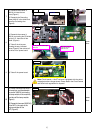
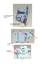
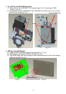
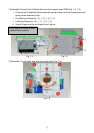
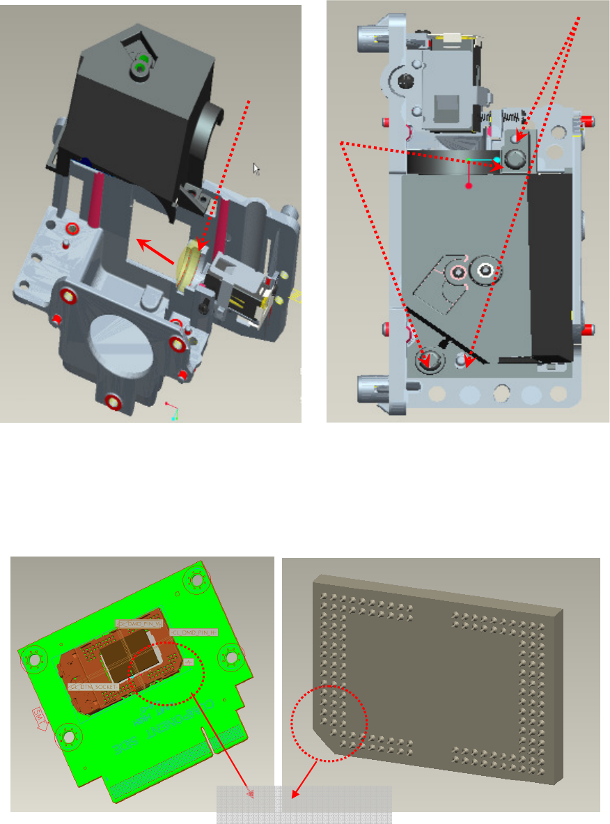
4. AL, HSG ILL and HSG DMD Assembly:
4.1 Placed “AL” on the “HSG DMD”. The “raised surface” of “AL” shall toward “DMD
direction” (Fig. 4-1).
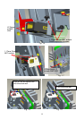
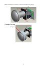
4.2 To assemble ”HSG ILL SUB Module” with “HSG DMD” and cover over on “AL” and the
then lock with screws(Fig. 4-2).
Fig. 4-1 Fig. 4-2
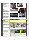
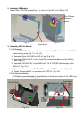
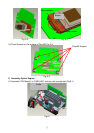
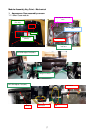
5. DMD and Chip B/D Module:
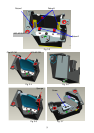
5.1. Judge Chip B/D and DMD alignment keying first (Fig. 5-1, 5-2).
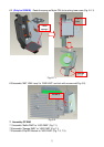
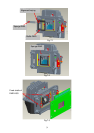
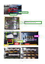
5.2. Alight keying and Assemble DMD to Chip B/D (Fig. 5-3).
5.3. Push DMD slightly and use screwdriver rotate clockwise button to lock (close notation)
DMD on Chip B/D (Fig. 5-4).
Fig. 5-1 Fig. 5-2
Alignment keying
AL
DMD Direction
Screw
Fixed shafts& holes