


6-4 Hardware Installation
Copyright © 2002 by LSI Logic Corporation. All rights reserved.
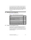
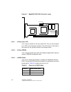
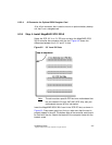
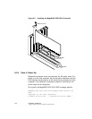
Figure 6.1 MegaRAID SCSI 320-0 Controller Layout
6.2.3.1 J2 Dirty Cache LED
J2 is a two-pin header for the dirty cache LED. This can be connected
to an LED on the computer enclosure. The LED will be lit when data in
the cache has not yet been written to the storage device.
6.2.3.2 J3 Clear EPROM
J3 is a two-pin header that clears the erasable progammable read-only
memory (EPROM) configuration data.
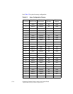
6.2.3.3 J4 BIOS Enable
J4 is a 2-pin header that enables or disables the MegaRAID onboard
BIOS. The onboard BIOS should be enabled (J4 unjumpered) for normal
board position. Table 6.3 contains the pinout for J4.
J2 J3 J4
Optional Backup
Battery Unit
Connector
J8
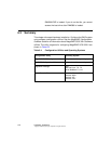
Table 6.3 Pinout for J4 BIOS Enable
J4 Setting Onboard BIOS Status
Unjumpered Enabled
Jumpered Disabled