


Chapter 3 45
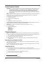
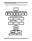
Disassembly Procedure Flowchart
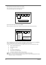
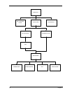
The flowchart on the succeeding page gives you a graphic representation on the entire disassembly sequence
and instructs you on the components that need to be removed during servicing. For example, if you want to
remove the system board, you must first remove the keyboard, then disassemble the inside assembly frame in
that order.
START
BATTERY
CDROM
MODULE
DIMM
COVER
MIDDLE
COVER
COMBO
MODULE
COVER
HINGE
CAP
TOUCH
PAD
LCD COAXIAL
CABLE
INVERTER
CABLE
KEYBOARD
MAIN UNITLCD MODULE
LCD CABLE
COVER
LCD BEZEL
SPEAKER
LCDINVERTER
LCD BRACKET
LCD COXIAL
CABLE
INVERTER
CABLE
HDD
MODULE