


54 Chapter 3
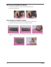
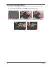
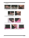
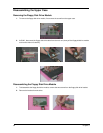
2. At CN9, remove the two screws from the LCD FPC cable, and then disconnect the LCD FPC cable from
the main board.
3. At CN8, disconnect the inverter cable from the main board.
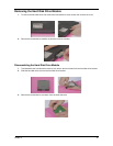
4. Remove the LCD module from the main unit.
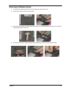
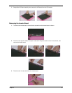
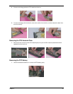
5. Remove the video capture kit cover from the LCD module on each side.
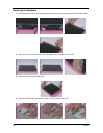
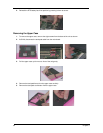
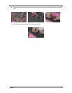
6. Remove the three LCD cushions as shown, next remove the three screws from the LCD bezel.
NOTE: If you have 12.1” or 13.3” LCD, you need to remove five LCD cushions and five screws.