


661 Brea Canyon Rd., Suite 3
Walnut, CA 91789
tel: 909.598.7388, fax: 909.598.0218
© Copyright 2009 Acnodes, Inc.
All rights reserved. Product description and product specifications
are subject to change without notice. For latest product information,
please visit Acnodes’ web site at www.acnodes.com.
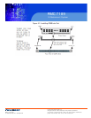
RMC 7189
1U Rackmount System
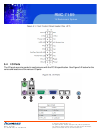
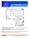
5-8 Connector Definitions
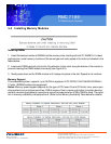
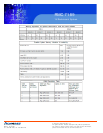
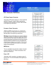
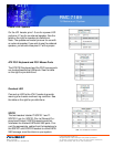
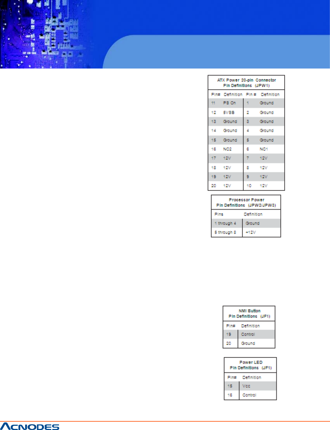
ATX Power Supply Connector
The primary ATX power supply con- nector meets the
SSI EPS 12V speci- fication. Make sure that the
orientation of the connector is correct. See the table
on the right for pin definitions.
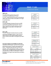
Processor Power Connector
JPW2 and JPW3 must also be con- nected to the
power supply to provide power for the processor(s).
See the table on the right for pin definitions.
Warning: To prevent damage to your power supply or
serverboard, please use a power supply that contains
a 20-pin and two 8-pin power connectors. Be sure to
connect these power connectors to the 20-pin and the
two 8-pin power connectors on your serverboard for
adequate power supply to your system. Failure to do
so will void the manufacturer warranty on your power
supply and serverboard.
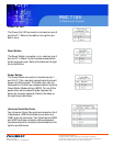
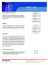
NMI Button
The non-maskable interrupt button header is located
on pins 19 and 20 of JF1. Refer to the table on the
right for pin definitions.
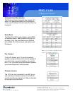
Power LED
The Power LED connection is located on pins 15
and 16 of JF1. Re- fer to the table on the right for pin
definitions.