661 Brea Canyon Rd., Suite 3
Walnut, CA 91789
tel: 909.598.7388, fax: 909.598.0218
© Copyright 2009 Acnodes, Inc.
All rights reserved. Product description and product specifications
are subject to change without notice. For latest product information,
please visit Acnodes’ web site at www.acnodes.com.
RMC 7189
1U Rackmount System
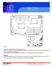
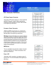
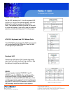
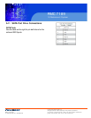
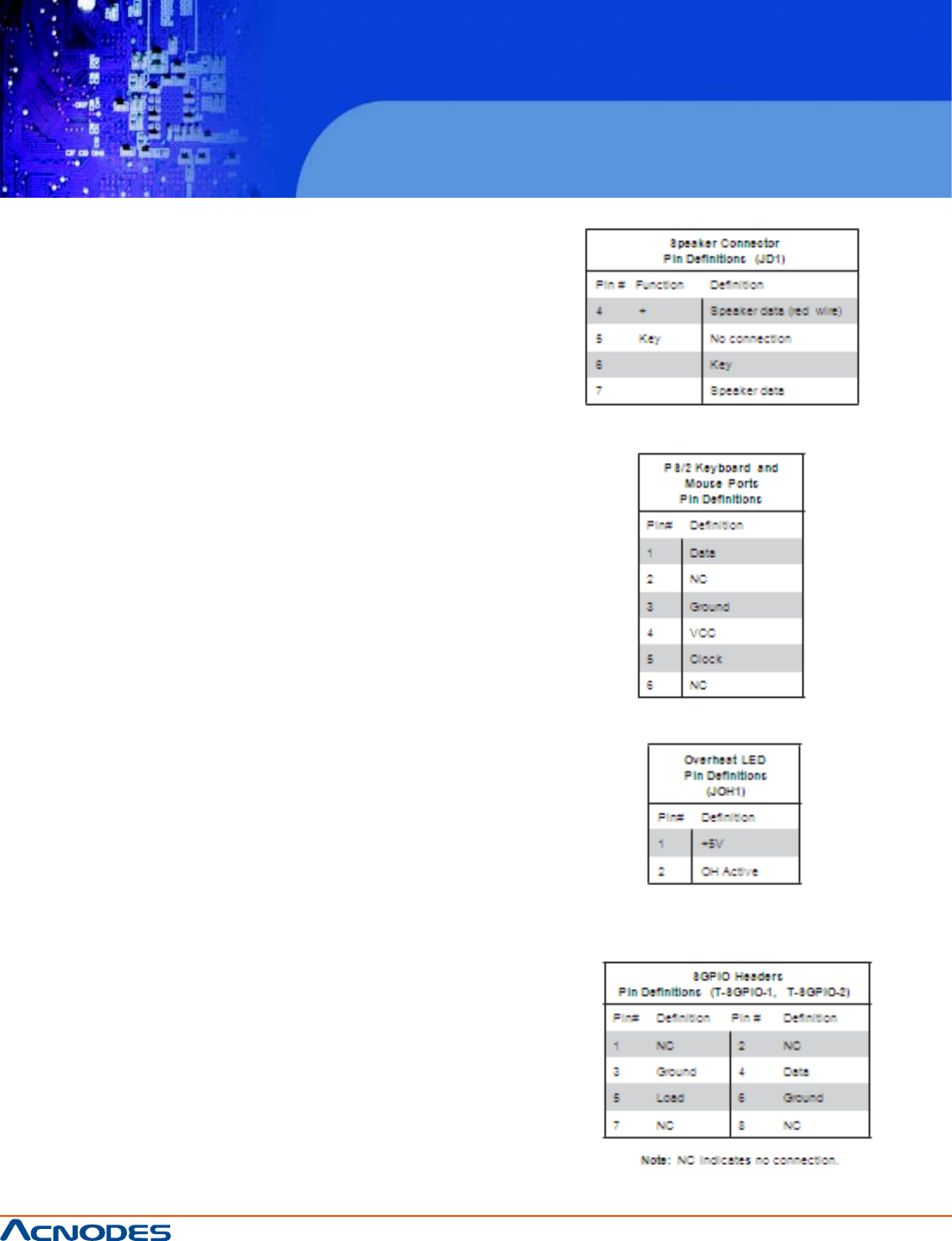
Power LED/ Speaker
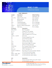
On the JD1 header, pins 1-3 are for a power LED
and pins 4-7 are for an external speaker. See the
table on the right for speaker pin definitions.
Note: The speaker connector pins are for use with
an external speaker. If you wish to use the onboard
speaker, you should close pins 6-7 with a jumper.
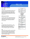
ATX PS/2 Keyboard and PS/2 Mouse Ports
The ATX PS/2 keyboard and the PS/2 mouse ports
are located beside the USB ports. See the table
on the right for pin definitions.
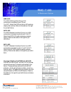
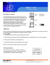
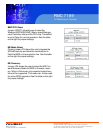
Overheat LED
Connect an LED to the JOH1 header to provide
warning of a chassis overheat- ing condition. See
the table on the right for pin definitions.
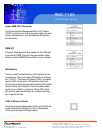
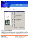
SGPIO
The two headers labeled T-SGPIO-1 and T-
SGPIO-2 are for SGPIO (Se- rial General Pur-
pose Input/Output). SGPIO supports serial link
interfaces for onboard SATA and SAS ports. Con-
nect the appropriate cables from the backplane to
the SGPIO1 and SGPIO2 headers to utilize SATA/
SAS manage- ment functions on your system.


