


RAID Controller Circuit Boards
52
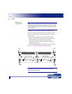
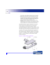
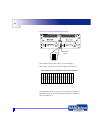
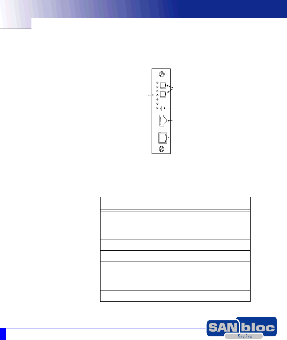
The main parts of the RAID Controller are described in
Figure 4-3.
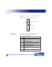
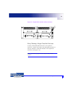
Figure 4-3 Main components of RAID controller
RAID Controller
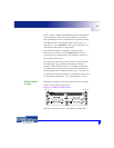
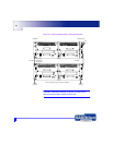
Status LEDs
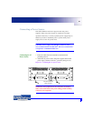
The RAID controller has 7 Status LEDs as shown above.
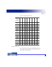
Table 6-1 describes what these LEDs signify.
Table 6-1 Controller Status LEDs
1
2
3
4
5
6
7
FC Host Connectors (SSF optical)
HSSDC Connector
Ethernet Connection
RS232
Status LEDs
LED Description
1 Yellow - Not Ready. Normally Off. Goes On during
power up sequence.
2 Green - Ready. Normally On
3 Green - Dirty Cache. On when there is data in cache.
4 Yellow - BBU Fault. Normally Off.
5 Green - Partner Fail. Normally Off
6 Green - Device Activity i.e. on drive channels. Flashes
with activity.
7 Green - Host Activity. Flashes with activity.