


iDP-3410 User’s Manual
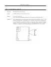
ESC "∗" m n1 n2 [d] n1 + 256 × n2
[Function] Specifying the bit image mode
[Code] <1B>H <2A>H m n1 n2 [d] n1 + 256×2
[Range] m = 0, 1
0 ≤ n1 ≤ 255
0 ≤ n2 ≤ 3
0 ≤ d ≤ 255
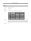
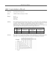
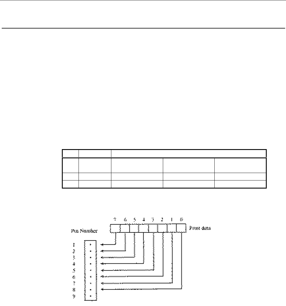
[Outline] This command specifies the bit image for the mode m as to the number of dots specified with
n1 and n2. Divide the number of dots printed by 256 and assume its quotient to be n2 and
remainder to be n1. Therefore, the number of horizontal dots will be n1 + 256 × n2.
If the bit image data is entered beyond the dot positions printable in one line, the surplus data
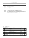
will be discarded. The following table shows the bit image modes for m.
Horizontal Direction
m
Vertical
Dots
Dot Density
Adjacent Dot
Setting
Total Dots
0 8 Single density Allowed 189
1 8 Double density Disallowed 378
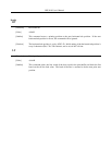
[Caution] If the value of m is beyond the conditions, the data subsequent to n1 will be processed as
normal data. Normal data processing will be restored after completing bit image print.