


iDP-3410 User’s Manual
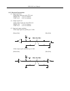
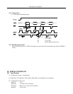
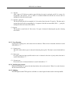
(1) Start bit
After a lapse of 1/2 bit from a mark-to-space fall edge, the state is read again, and if it is a space, it is
recognized as the start bit. If it is a mark, it is assumed neither the start bit nor an error, and it is
attempted to detect the start bit again.
(2) Data bit + parity bit
The data bit and parity bit are sampled for 1 bit worth of time from the 1/2 start bit. The then state is
assumed the data for the corresponding bit. A sequence of the bits are named Bit 0, Bit 1, ..., parity bit,
starting from the one closest to the start bit.
(3) Stop bit
The stop bit is a mark level of 1 bit or more. If a space is detected in detecting the stop bit, a framing
error results.
10.3.3 Error Detection
A parity error, framing error, and overrun error are detected. When an error is detected, that data is stored
in the buffer as "?".
(1) Framing error
This error results when a space is detected in detecting the stop bit. That data is stored in the buffer as
"?".
(2) Parity error
If a parity check has been specified and an error is detected at the time of parity check, that data is
stored in the buffer as "?".
(3) Overrun error
If an overrun error is detected, that data is stored in the buffer as "?".
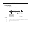
10.3.4 Data Receiving Control
When the DTR signal is a space, the data from the host side can be received. When it is a mark, however,
the data cannot be received.
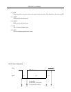
10.3.5 Buffering
The DTR signal and the TXD signal are available as a control signal for data transfer to the input buffer.