


iDP-3410 User’s Manual
CONTENTS
1. OUTLINE........................................................................................................................................................16
1.1 Features................................................................................................................................................................ 16
1.2 Unpacking............................................................................................................................................................ 16
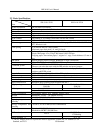
2. BASIC SPECIFICATIONS .............................................................................................................................17
2.1 Model Classifications.......................................................................................................................................... 17
2.2 Basic Specifications............................................................................................................................................. 18
2.3 Paper Specifications ............................................................................................................................................ 19
2.3.1 Recommended Paper................................................................................................................................ 19
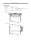
2.3.2 Printing Position....................................................................................................................................... 19
2.3.3 Cutter Layout...................................................................................................................................................... 19
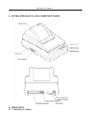
3. OUTER APPEARANCE AND COMPONENT PARTS...................................................................................20
4. OPERATION..................................................................................................................................................21
4.1 Connecting AC Adapter ...................................................................................................................................... 21
4.2 Connecting Interface Cable................................................................................................................................. 22
4.3 Connecting Drawer Kick-Out Connector............................................................................................................ 22
4.4 Setting the Cassette Ribbon................................................................................................................................. 23
4.5 Inserting the Paper............................................................................................................................................... 24
4.6 How to Remove Remaining Paper Roll .............................................................................................................. 26
4.7 Removing Paper Jam........................................................................................................................................... 26
4.8 Operation Panel and Display of Error ................................................................................................................. 27
4.9 Operation Flow at Power-on ............................................................................................................................... 28
5. DIP SWITCH SETTING.................................................................................................................................29
5.1 Location of DIP Switch....................................................................................................................................... 29
5.2 DIP Switches Setting........................................................................................................................................... 30
6. PRESET JUMPER SETTING..........................................................................................................................32
6.1 Location of Preset Jumper................................................................................................................................... 32
6.2 Preset Jumper Table ............................................................................................................................................ 32
7. MODE SETTING METHOD ..........................................................................................................................33
8. INPUT BUFFER BACKUP FUNCTION ........................................................................................................34
8.1 Buffer Size........................................................................................................................................................... 34
8.2 Input Buffer Backup............................................................................................................................................ 34
8.3 Clearing the Input Buffer..................................................................................................................................... 34
9. PARALLEL INTERFACE ..............................................................................................................................35
9.1 Specifications ...................................................................................................................................................... 35
9.2 Connector's Pin Configuration ............................................................................................................................ 35
9.3 Input and Output Signals..................................................................................................................................... 36
9.3.1 Input and Output Signals.......................................................................................................................... 36
9.3.2 Electrical Characteristics.......................................................................................................................... 37
9.3.3 Timing Chart............................................................................................................................................ 38
9.3.4 Data Receiving Control............................................................................................................................ 38
10. SERIAL INTERFACE...................................................................................................................................39
10.1 Specifications ...................................................................................................................................................... 39
10.2 Connector's Pin Configuration ............................................................................................................................ 40