


iDP-3410 User’s Manual
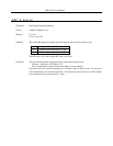
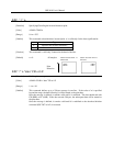
ESC "p" m n1 n2
[Function] Specifying the pulse generation
[Code] <1B>H <70>H m n1 n2
[Range] 0 ≤ m ≤ 1
0 ≤ n1 ≤ n2 ≤ 255
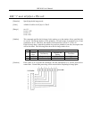
[Outline] This command outputs the signals specified with n1 and n2 to the connector pins.
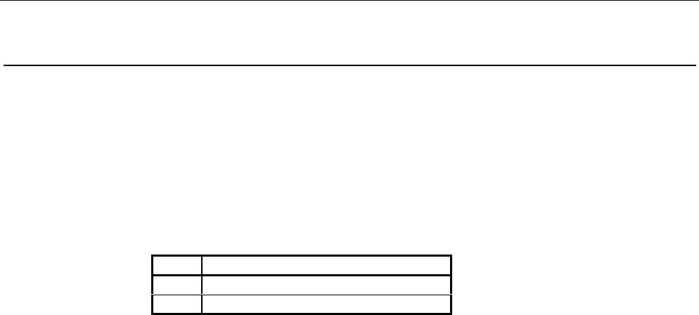
m Connector Pin
0 Drawer kick connector No. 2 pin
1 Drawer kick connector No. 5 pin
The ON time is n1×2 mS and the OFF time is n2×2 mS.
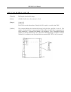
[Caution] The user should consider driving the drawer at the following duty ratio.
ON time ÷ (ON time + OFF time) ≤ 0.2
(It is recommended to make n2 four times higher or more than n1.)
The drawer kick-out solenoid should have a resistance value of 36Ω or more. Do not use a
lower one because an overcurrent will flow. For the drawer power, be sure to use the printer
power (Drawer kick-out connector No. 4 pin).