


12 Section 61182007L1-5, Issue 1 61182007L1-5A
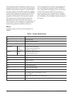
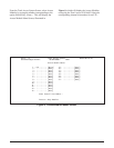
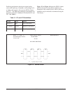
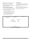
Predicting performance based upon signal quality
varies with each loop. Generally, a noise margin of 0
or higher will support a bit error rate (BER) of better
than 10-7. The following guidelines correspond to the
operation of the LTU faceplate LEDs labeled LP1 and
LP2. See Table 3.
Table 3. LP1 and LP2 Guidellines
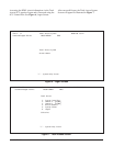
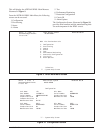
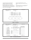
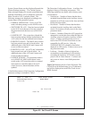
Figure 15. Alarms Screen
Shelf: 1 Slot: 5 Total Access System 04/07/01 09:16
Unacknowledged Alarms: MAJOR MINOR
Circuit ID:
Alarms
NO ALARM CONDITIONS
_____ _____ _____ _____
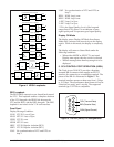
| LTU | |REG 1| |REG 2| | NTU |
| | | | | | | |
--->| |<===>| |<===>| |<===>| |<—-
| | | | | | | |
NET | | | | | | | | CUST
| | | | | | | |
<---| |<===>| |<===>| |<===>| |—>
| | | | | | | |
|_____| |_____| |_____| |_____|
‘?’ - System Help Screen
nigraMroloCytilauQ
0<nigraMdeRytilauQpooLrooP
2<nigraM<0wolleYytilauQpooLlanigraM
2>nigraMneerGytilauQpooLdooG
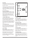
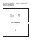
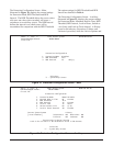
Figure 15 and Figure 16 depict the HDSL Alarms
and Test Screens. Current alarm conditions are
displayed on the Alarms Screen, while a self test or
loopbacks may be initiated or terminated using the
Test Screen.