


2 Section 61182007L1-5, Issue 1 61182007L1-5A
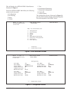
C A U T I O N !
SUBJECT TO ELECTROSTATIC DAMAGE
OR DECREASE IN RELIABILITY.
HANDLING PRECAUTIONS REQUIRED.
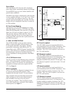
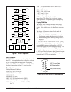
The HDSL local loop operates as two independent
subsystems each operating over a single twisted pair.
The LTU communicates over these two twisted pairs
to the HDSL Transceiver Unit - Remote end (NTU).
Each subsystem carries half of the total bandwidth
along with a small amount of overhead used for
maintenance and performance monitoring.
System power and alarm bus connections are made
through the backplane of the Total Access 3010 shelf.
E1 and HDSL signals are connected through the 50-
pin shelf connectors related to each individual slot.
The LTU contains onboard fuses. If a fuse opens, it
supplies a -48 Vdc voltage to the fuse alarm bus and
all front panel indicators will be Off. These fuses are
not field replaceable.
The Total Access 3010 LTU uses a DC-to-DC
converter to derive its internal logic and span
powering voltages from the -48 Vdc office supply.
The Total Access 3010 LTU can span power REGs
and NTUs as listed above. When used with REGs and
NTUs, the LTU can span power one REG and an
NTU at less than -120 Vdc. Span powering voltages
meet all requirements of IEC 950.
REVISION HISTORY
This is the first issue of this practice. Future changes
to this document will be summarized in this
paragraph.
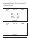
2. INSTALLATION
After unpacking the unit, inspect it for damage. If
damage is discovered, file a claim with the carrier,
then contact ADTRAN. See Warranty and Customer
Service.
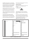
The Total Access 3010 LTU occupies one line card
slot in a Total Access 3010 shelf. Power and alarm
signals are provided to the card through the backplane
of the shelf. E1 and HDSL loop signals are connected
to the mass termination shelf connectors
corresponding to the slot the unit occupies. See
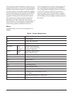
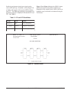
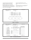
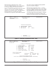
Figure 2 for LTU edge connector wiring.
Figure 2. LTU Edge Connector Wiring
1
2
3
4
5
6
7
8
9
10
11
12
13
14
15
16
17
18
19
20
21
22
23
24
25
26
27
28
29
30
31
32
1
2
3
4
5
6
7
8
9
10
11
12
13
14
15
16
17
18
19
20
21
22
23
24
25
26
27
28
29
30
31
32
1
2
3
4
5
6
7
8
9
10
11
12
13
14
15
16
17
18
19
20
21
22
23
24
25
26
27
28
29
30
31
32
P2, Row A P2, Row B P2, Row C
- 48 Volt return
Chassis ground
Chassis ground
HDSL Loop 2 Ring (facility)
Fuse alarm
Receive G.703 Ring backup connection
Transmit G.703 Ring backup connection
Receive G.703 Ring normal connection
Transmit G.703 Ring normal connection
- 48 Volt return
- 48 Volt DC A
- 48 Volt DC A
HDSL Loop 1 Ring (facility)
HDSL Loop 1 Tip (facility)
HDSL Loop 2 Tip (facility)
Receive G.703 Tip backup connection
Transmit G.703 Tip backup connection
Receive G.703 Tip normal connection
Transmit G.703 Tip normal connection
- 48 Volt DC B
- 48 Volt DC B