


61182007L1-5A Section 61182007L1-5, Issue 1 B-3
3. INSTALL THE LTU
The Total Access 3010 LTU delivers an E1 signal
over an HDSL local loop. The local loop in the H-LSS
configuration includes two independent 4-wire
circuits. The two LTUs communicate to their
respective remote units, the NTUs. When an H-LSS
switch occurs, the AUX circuit takes over transmitting
the data load from the MAIN circuit until the MAIN
circuit is restored.
3.1 Install The LTUs into Total Access
3010
Electronic modules can be damaged by static
electrical discharge. Before handling modules,
wear an antistatic discharge wrist strap to
prevent damage to electronic components.
Place modules in antistatic packing material
when transporting or storing. When working
on modules, always place them on an
approved antistatic mat that is electrically
grounded.
3.1.1 Gently but firmly push the LTU into
the appropriate odd-numbered slot
(which will be the MAIN HDSL
circuit). Compatible slots can be any
slot pair that starts with an odd number
(MAIN) and includes the adjacent (to
the right) even-numbered slot (AUX).
Compatible slot pairs are further
designated by the bracket notation
around the slot pairs on the silk screen
just below the physical slots on the
front of the Total Access 3010.
Simultaneous thumb pressure at the
top (above the PWR LED) and bottom
(below the ACT LED) of the unit will
ensure a good seat of the LTU pins
into the backplane connector. Repeat
this step for the AUX LTU to be
installed in the adjacent (even, to the
right) slot.
3.1.2 Push the ejector tab up and closed
against the LTU faceplate.
3.2 Provision the LTU
If Module Auto-Provisioning is enabled on
the SCU, and if the new cards are of the same
type as the former, the provisioning of the
former access cards of the two Total Access
3010 slots will be written to the new access
cards upon installation.
If this is an initial installation, the units will
require provisioning to appropriately
configure them out of the factory default
states.
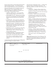
3.2.1 Logon to Total Access system.
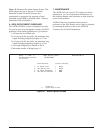
3.2.2 Check to ensure the LTU line cards are
correctly provisioned according to
circuit parameters. Under the
Provisioning Menu, set numbered
option, Network Source, to Auto
MUX. This option causes the LTU to
look to the ON-LINE MUX for its data
in the event of a protection switch
between the MUX modules.
3.2.3 Ensure the provisioning of both the
MAIN and AUX LTUs is identical,
except for the following options:
a. Provision the MAIN unit to
OOS-M mode.
b. Provision the AUX unit to the
OOS-U mode.
3.2.4 Enable protection switching.
a. Access the MAIN Menu of the
LTU in the odd-numbered (MAIN)
slot.
b. Select Option 7, Protection
Configuration.
c. Select Option 1, Protection Mode.
d. To enable protection switching,
select Option1, Enable.
Unless the AUX circuit is in the
OOS-U mode, the operator will
not be able to change the
Protection mode of the MAIN
LTU.
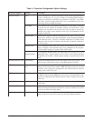
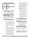
e. Set Options 2 and 3, BER
Threshold and BER Interval (see
Table 2).
f. Back out of the menu for the
MAIN slot and access the LTU in
the even-numbered (AUX) slot.
g. Select Option 7, Protection
Configuration.
h. Option 1, Protection Mode, will
have been set to AUTO. If you
desire to provision a different
H-LSS mode, select Option 1, and
choose between Auto, Manual
AUX, Manual Main, or Auto Hold.
i. Set Options 2-7 as desired on the
AUX unit. (see Table 2).