


4 Section 61182007L1-5, Issue 1 61182007L1-5A
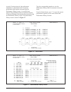
Status Mode
After selecting the LTU from the SCU, the display
enters Status mode. It alternately displays loop margin
for each HDSL loop, any active alarm condition, and
general status conditions.
The HDSL loop margin is displayed for each loop that
is active with the messages “1=xx” and “2=xx” where
xx is the HDSL loop margin for that loop. The loop
margin is held on the display for 2 seconds. The loop
margin will not be displayed if that loop is in start-up
or LOS condition.
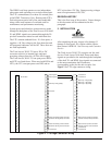
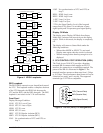
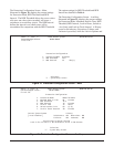
E1 Core Frame Mapping
The function of E1 core frame mapping is to assign
2048 kbps framed E1 data to a 2304 kbps core frame
filled with 2048 kbps data. This converts a 32-byte E1
frame into a 36-byte core frame (a ratio of 1:1.125).
The extra four bytes are filled with TSO, TS16, or
AIS data. Once the 36-byte core frame data block
reaches the HDSL loops, the data is split between the
two HDSL loop pairs.
4. HDSL SYSTEM TESTING
The ADTRAN HDSL system provides extensive
ability to monitor the status and performance of the
G.703 signals and HDSL loop signals. Detailed
performance monitoring is provided by the V.24
Control Port on the ADTRAN System Controller Unit
(SCU). These features are valuable in troubleshooting
and isolating any system level problems that may
occur at installation or during operation of the HDSL
system.
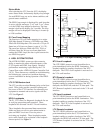
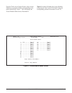
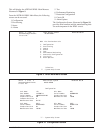
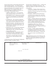
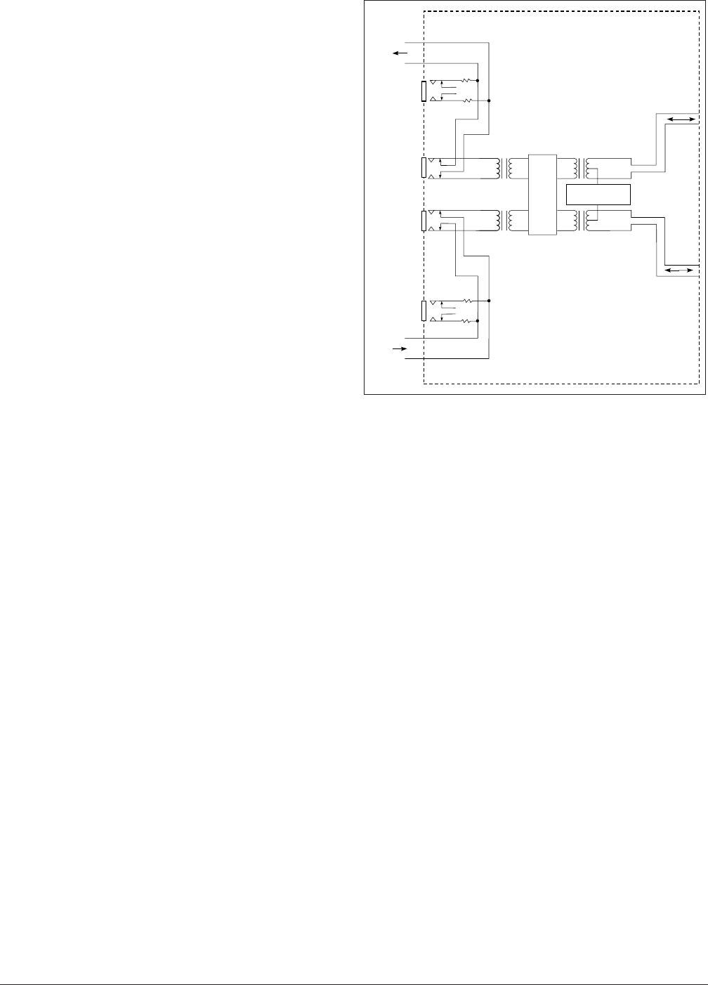
LTU G.703 Bantam Jack
The LTU provides two dual Bantam jacks on the front
panel. These jacks provide a metallic splitting and
test access of the G.703 interface for connecting test
equipment to transmit and receive signals with the
LTU. See Figure 3.
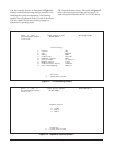
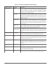
HDSL Loopbacks
The E1 LTU offers five diagnostic loopbacks for use
in verifying proper data path operation. These
loopbacks are activated via the V.24 craft interface.
These loopbacks disrupt normal data transmission.
Make sure that you receive prior authorization to
place an HDSL circuit out of service prior to
activating any loopback. These loopbacks remain
active until cleared or by expiration of the loopback
timeout period. See Figure 4.
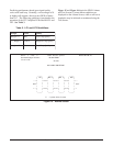
NTU Local Loopback
The NTU HDSL transceivers are looped back at a
point immediately before the HDSL termination. This
loopback enables a complete checkout of the NTU
data path. The NTU Local Loopback is activated via
the V.24 craft interface.
NTU Remote Loopback
The NTU HDSL transceivers are looped back at a
point immediately before the G.703 termination. This
loopback enables a complete checkout of the NTU
data path, the HDSL link, and the LTU data path. The
NTU Remote Loopback is activated via the V.24 craft
interface.
LTU Local Loopback
The LTU HDSL transceivers are looped back at a
point immediately before the HDSL termination. This
loopback enables a complete checkout of the LTU
data path. The LTU Local Loopback is activated via
the V.24 craft interface.
LTU Remote Loopback
The LTU HDSL transceivers are looped back at a
point immediately before the G.703 termination. This
loopback enables a complete checkout of the NTU
data path, the HDSL link, and the LTU data path. The
LTU Remote Loopback is activated via the V.24 craft
interface.
Figure 3. LTU Span Powering Diagram
G.703
MON
RX
LTU
DATA
PUMP
LOOP DC
POWER SOURCE
G.703
T1
R1
G.703
T
R
HDSL
LOOP 1
HDSL
LOOP 2
LTU
HDSL
LOOP 1
HDSL
LOOP 2
EQ
RX
G.703
MON
TX
EQ
TX