


B-2 Section 61182007L1-5, Issue 1 61182007L1-5A
NOTE
Only one DS3 MUX is required for any data
circuit to be operational. Two modules are used
for electronics redundancy of the DS3 circuit.
2.2 Provision the DS3 MUX
NOTE
There are no settings on the SCU that will affect
APS operation of either the DS3 MUX units or
the LTU line cards.
2.2.1 Logon to Total Access system.
2.2.2 If you are building a new DS3 circuit,
provision the DS3 MUX modules
according to circuit parameters. If the
HDSL H-LSS circuit is to be turned up
in an existing Total Access 3010 with
DS3 feed, assume that the parameters
have already been set for the DS3
circuit. Disregard this step and
continue.
2.2.3 When channel mapping the DS3 MUX
to individual slots configured for
protection switching, it is necessary to
map a channel only to the MAIN (odd-
numbered) slot. If a fault condition
occurs and a protection switch is made
from the MAIN circuit to the AUX
circuit, the channel is temporarily
mapped by the DS3 MUX into the
AUX (even-numbered) slot and a
Failure notice attached to the MAIN
(odd) slot. Follow the steps below for
mapping a channel to the MAIN slot.
For this procedure, the technician
needs to know which embedded G.703
in the incoming DS3 data stream to
map to the appropriate APS slot in the
Total Access 3010. Do not continue
without this information. In a newly
installed DS3 MUX, thathas not been
changed from factory defaults, the
embedded G.703s in the DS3 will be
mapped to the like-numbered slot (i.e.
G.703#1 to Slot 1, G.703#2 to Slot 2,
up to G.703#28 to Slot 28).
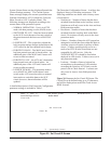
a. Access the Main Menu of the
DS3 MUX module and select
Option 8, Channel Mapping.
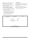
b. At the bottom of the screen where
you see “Selection or Enter
Mapping (E1#/Slot#)”, enter the
number of the embedded G.703
followed by “/” and the
appropriate slot number, then
<Enter>. This action will assign
the desired G.703 to the slot in the
Total Access 3010.
WARNING
Assigning the incorrect embedded G.703 from
the DS3 to a slot in the Total Access 3010 could
disrupt existing traffic.
2.2.4 APS configuration of the DS3 MUX
units is NOT required for the LTUs to
be in H-LSS configuration. The two
APS configurations operate
independently of each other.
NOTE - APS Faceplate Pushbutton -
1. When activated with the Test/Enable switch
on the Offline unit, it forces a switch to protection.
(Offline MUX becomes Online MUX).
2. When activated with the Test/Enable switch
from the ONLINE unit, it toggles the APS
Lockout Status.
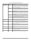
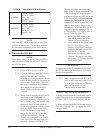
Table B-1. Faceplate LED Indicators
ENILNO
wolleY-REWOP
neerG-SUTATS
ffO-TSET
ffO-TUOKCOL
neerG-ENILNO
ENILFFO
wolleY-REWOP
neerG-SUTATS
ffO-TSET
ffO-TUOKCOL
ffO-ENILNO