


16 Section 61182007L1-5, Issue 1 61182007L1-5A
System Current Status are also displayed beneath the
Current Settings summary. The Current System
Status message displays the current operational state
(Normal, Switched to AUX, Locked Out, Forced to
Main, Forced to AUX, Locked to Main). The
following messages are displayed according to the
current status of the protection system.
• NORMAL OPERATION – Unit is in AUTO
mode with data passing over the MAIN circuit.
• SWITCHED TO AUX – Data has been switched
to the AUX circuit because of an auto switch or
the protection mode has been set to MANUAL
AUX.
• LOCKED OUT – The system has violated the
lock-in option settings and has locked data to the
AUX circuit for the user-defined lock-in hours.
• FORCED TO MAIN – The MAIN unit’s button
has been pressed once and is forced online. An
additional press of the MAIN unit’s button will
revert to software control.
• FORCED TO AUX – the AUX unit’s button has
been pressed once and is forced online. An
additional press of the AUX unit’s button will
revert to software control.
• LOCKED TO MAIN – The protection mode is
set to MANUAL MAIN which doesn’t auto
switch to the AUX circuit but relies on manual
intervention to switch the data to the AUX
circuit; however, alarm indications will be
updated.
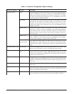
A detailed description of the Protection Configuration
parameter settings is included in Table 3.
The Protection Configuration Screen – Auxiliary also
displays a history of switching occurrences. The
following conditions are shown with a history count
of occurrences:
• Switchovers – Number of times data has been
switched from the Main to the Auxiliary circuit.
Switchovers will only occur in the Auto and Auto
Hold protection modes.
• Reversions – Number of times data has been
switched from the Auxiliary back to the Main
circuit. Reversions will only occur in the Auto
protection mode.
• Failures – Number of times the APS system has
attempted to switch data from either the Main to
Auxiliary circuit or from the Auxiliary to Main
circuit. A failure would typically occur as a
result of an HTU-R in the circuit that was not
compatible for APS service. Only the
1245026LX HTU-R’s should be used when
deployed in APS circuits. Failures can occur in
any protection mode.
• Lockouts – Number of times a lockout has
occurred due to the number of APS switches
exceeding the Switch to AUX Limit over the
preset Lock-in Check Interval. Lockouts can
only occur in Auto or Auto Hold protection
modes.
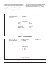
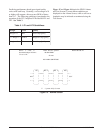
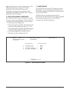
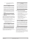
Figure 20 illustrates the Set Circuit ID Screen. The
Circuit ID can be defined using up to 25 characters,
and will be displayed on each of the Total Access
HDSL Screens.
Figure 20. Set Circuit ID Screen
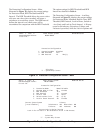
Shelf: 1 Slot: 5 Total Access System 04/07/01 09:21
Unacknowledged Alarms: MAJOR MINOR
Circuit ID:
Set Circuit ID
Enter ID:
‘?’ - System Help Screen