


61182007L1-5A Section 61182007L1-5, Issue 1 A-1
Appendix A
HDSL H-LSS Circuit Configuration and Turnup
for G.703 Fed Systems
Introduction
This section provides step-by-step instructions for the
configuration and turnup of an HDSL Loop Support
System (H-LSS) circuit on an HDSL loop fed from
the network via individual G.703. Configuration
procedures include installing appropriate line and
remote cards, configuring the Total Access LTU cards
for protection switching operation and enabling the
protection switching feature.
Protection pairs on the Total Access 3010 system are
adjacent odd-even slots, indicated on the Total Access
3010 front shelf screening. The odd slot on the left is
the MAIN circuit; the even slot to the right is the
AUX, or backup circuit.
Prerequisite Procedures
Before beginning the configuration and turnup
procedure described in this NTP, the user should
ensure that a Total Access 3010 shelf is properly
installed and wired for G.703 network feeds. Also,
ensure the SCU is installed and provisioned.
NOTE
Valid protection pairs are the adjacent odd-even
slots in the Total Access 3010 shelf, and are
further designated by the “brackets” on the lower
front silkscreen of the Total Access 3010 chassis.
The left (odd-numbered) slot in the pair is the
MAIN; the right (even-numbered) slot is the
AUX circuit for the pair. Thus, Slots 1 and 2 are
a valid protection pair, but Slots 6 and 7 are not.
The pair must have the odd-numbered slot to the
left in the pair.
NOTE
This procedure assumes that the technician
turning up the protected circuit knows which
pair of slots has been assigned to the circuit, and
that a single G.703 signal from the appropriate
source, generally a G.703 cross connect, has
been routed and wired to the appropriate pairs of
pins on backplane connectors labeled Pair 7 and
Pair 8. For a protected circuit, the appropriate
pin pairs that should receive the G.703 from the
network are the odd numbered pins
corresponding to the MAIN, odd numbered slot.
Materials Required
• Total Access 3010 chassis installed and wired,
with SCU.
• Two Total Access 3010 LTUs.
• Two protection switching capable NTUs. These
NTUs are the following - 1246035L1 T200
mechanics.
• One dual-slot remote housing, ADTRAN P/N
1245034L2.
1. INSTALL THE LTUs INTO TOTAL ACCESS
3010
Electronic modules can be damaged by static
electrical discharge. Before handling modules, wear
an antistatic discharge wrist strap to prevent damage
to electronic components. Place modules in antistatic
packing material when transporting or storing. When
working on modules, always place them on an
approved antistatic mat that is electrically grounded.
1.1 Gently but firmly push the LTU into the
appropriate odd-numbered slot (which will be
the MAIN HDSL circuit). Compatible slots
can be any slot pair that starts with an odd
number (MAIN) and includes the adjacent (to
the right) even-numbered slot (AUX).
Compatible slot pairs are further designated
by the bracket notation around the slot pairs
on the silk screen just below the physical slots
on the front of the Total Access 3010.
Simultaneous thumb pressure at the top
(above the PWR LED) and bottom (below the
ACT LED) of the unit will ensure a good seat
of the LTU pins into the backplane connector.
Repeat this step for the AUX LTU to be
installed in the adjacent (even, to the right)
slot.
1.2 Push the ejector tab up and closed against
the LTU faceplate.
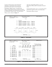
2. PROVISION THE LTU
If Module Auto-Provisioning is enabled on the SCU,
and if the new cards are of the same type as the
former, the provisioning of the former access cards of
the two Total Access 3010 slots will be written to the
new access cards upon installation.