


Section 3 Engineering Guidelines TRACER 5045 System Manual
26 © 2003 ADTRAN, Inc. 612805045L1-1A
1. EQUIPMENT DIMENSIONS
The TRACER 5045 unit is 17.22” W, 9.34” D, and 1.72” H, weighs 7 lbs, and can be used in rack-mount
configurations.
2. POWER REQUIREMENTS
The TRACER 5045 system has a maximum power consumption of 23 Watts and a maximum current draw
of 1.1 Amps (at 21 VDC).
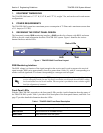
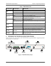
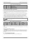
3. REVIEWING THE FRONT PANEL DESIGN
The front panel contains RSSI monitoring interface, a GND interface for reference with RSSI, and status
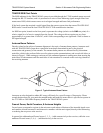
LEDs to provide visual information about the TRACER 5045 system. Figure 1 identifies the various
bantam interfaces and the LEDs.
Figure 1. TRACER 5045 Front Panel Layout
RSSI Monitoring Interface
The RSSI voltage is a function of the signal strength at the receiver and is used to measure the received
signal strength. RSSI varies approximately from 0 to greater than 4 Volts (V), with 0V corresponding to a
weaker received signal and 4V or better corresponding to a stronger received signal.
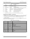
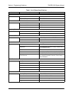
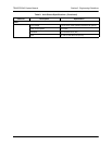
Front Panel LEDs
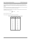
With the TRACER 5045 powered-on, the front panel LEDs provide visual information about the status of
the TRACER 5045 system. Table 1 provides a brief description of the front panel features, and Table 2 on
page 27 provides detailed information about the LEDs.
The voltage level present at the RSSI test point represents only a relative signal level of
receive strength from the far end. No direct correlation can be made between RSSI voltage
levels and actual receive levels in dBm. This test point is provided to assess relative signal
level for alignment of antennas.
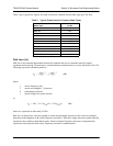
Table 1. TRACER 5045 Front Panel Description
Feature Description
RSSI Interface DC voltage indicating strength of the received signal at the antenna
GND Interface
Ground reference for the RSSI interface
Status LEDs Status information about the system
LAN WAN PLAN RF
1
GNDRSSI
2 3 4
TRACER 5045
Status LEDs
GND
RSSI