


TRACER 5045 System Manual Section 4, Network Turnup Procedure
612805045L1-1A © 2003 ADTRAN, Inc. 37
4. CHANNEL SELECTION
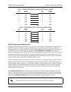
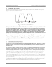
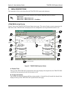
The FCC has allocated 125 MHz of spectrum in the 5.8 GHz band where the TRACER 5045 operates.
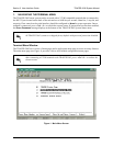
Figure 1 illustrates the bandwidth division.
Figure 1. 5.8 GHz Bandwidth Division
To designate the utilization of the ISM bandwidth, there are two different channel plans, labeled A and B.
The letter of each channel plan setting is preset by the factory and refers to the physical configuration of
the diplexer filter inside the chassis. The channel plan (A or B) refers to which half of the band the radio
transmits in. For example, a Plan A radio will transmit in Channel A and receive in Channel B. A Plan B
radio will transmit in channel B and receive in Channel A. The transmitter at one end of the link must
transmit in the lower portion of the spectrum and receive in the upper portion. Consequently, the receiver at
the other end must receive in the lower portion and transmit in the upper portion.
The letter of the channel plan (A or B) must be different on both ends. Shipment of a link will consist of
one Plan A and Plan B unit. The channel plan of the unit may be changed in the field, if necessary, by
rewiring the internal diplexer. Contact ADTRAN Technical Support for more information on this
procedure.
5. GROUNDING INSTRUCTIONS
The following provides grounding instruction information from the Underwriters’ Laboratory UL 60950
Standard for Safety of Information Technology Equipment Including Electrical Business Equipment, of
December, 2000.
An equipment grounding conductor that is not smaller in size than the ungrounded branch-circuit supply
conductors is to be installed as part of the circuit that supplies the product or system. Bare, covered, or
insulated grounding conductors are acceptable. Individually covered or insulated equipment grounding
conductors shall have a continuous outer finish that is either green, or green with one or more yellow
stripes. The equipment grounding conductor is to be connected to ground at the service equipment.
The attachment-plug receptacles in the vicinity of the product or system are all to be of a grounding type,
and the equipment grounding conductors serving these receptacles are to be connected to earth ground at
the service equipment.
A supplementary equipment grounding conductor shall be installed between the product or system and
ground that is in addition to the equipment grounding conductor in the power supply cord.
A
57475725MHz 5850MHz
B
5827