


TRACER 5045 System Manual Section 5 User Interface Guide
612805045L1-1A © 2003 ADTRAN, Inc. 45
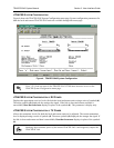
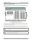
>TRACER SYSTEM CONFIGURATION
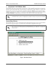
Figure 4 shows the TRACER 5045 System Configuration menu page. System configuration parameters for
both the local and remote TRACER 5045 units are available through this menu page.
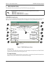
Figure 4. TRACER 5045 System Configuration
>TRACER SYSTEM CONFIGURATION > RX POWER
Displays the approximate receiver levels (for both the local and remote units) using a series of symbols (#).
The more symbols (
#) displayed, the stronger the signal. If the link is down and remote end data is
unavailable,
DATA NOT AVAILABLE displays in place of the symbols (#). This parameter is display only.
>TRACER SYSTEM CONFIGURATION > TX POWER
Allows the transmitter levels (for both the local and remote units) to be adjusted. The current transmitter
level is displayed using a series of symbols (
#). The more symbols (#) displayed, the stronger the signal. If
the link is down and remote end data is unavailable,
DATA NOT AVAILABLE displays in place of the symbols
(
#).
Press <1> from any menu in the TRACER 5045 VT100 menu structure to access the
TRACER System Configuration menu page.
Reducing the transmitter power of the remote TRACER 5045 could negatively impact the
TRACER RF link.