


Section 3 Engineering Guidelines TRACER 5045 System Manual
30 © 2003 ADTRAN, Inc. 612805045L1-1A
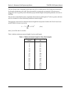
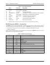
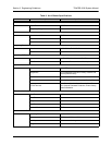
Table 5 contains the wiring diagram needed for connecting the TRACER 5045 RS-232 interface to a
modem using the null modem adapter.
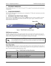
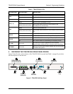
10/100BaseT/TX Connections (RJ-48C)
The physical Ethernet interfaces are provided by four RJ-48C jacks that deliver 10/100BaseT/TX
interfaces for LAN connectivity. Each port has a green
LINK LED to indicate a valid link and an amber
ACT LED that blinks with data activity on the interface.
Alarm Contacts (Plug-In Terminal Block)
Normally open (NO) and normally closed (NC) alarm contacts are provided on the rear panel of the
TRACER 5045 system. In normal operation, the NC contact is electrically connected to the common
contact (COM) and the NO contact is isolated. During an alarm condition, the NC contact becomes
isolated and the NO is electrically connected to COM. This allows alarm conditions to be reported to
external alarm monitoring systems.
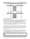
The null modem interface must route Carrier Detect (CD) on pin 8 directly from the
modem. When using the RS-232 interface for modem control, the modem must source CD
only when actually connected to a carrier.
Table 5. TRACER 5045 (DCE) to Modem (DCE - DB-25)
PIN NAME PIN NAME
2 TX 3 RX
3 RX 2 TX
4 RTS 5 CTS
5 CTS 4 RTS
6 DSR 20 DTR
7 GND 7 GND
8 CD 8 CD
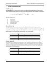
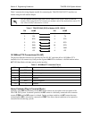
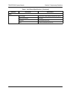
Table 6. 10/100BaseT/Tx Interface Pinout
PIN NAME DESCRIPTION
1
TX1 Transmit positive
2 TX2 Transmit negative
3 RX1 Receive positive
4,5 — Unused
6 RX2 Receive negative
7, 8 — Unused