


Section 4, Network Turnup Procedure TRACER 5045 System Manual
38 © 2003 ADTRAN, Inc. 612805045L1-1A
The supplementary equipment grounding conductor shall not be smaller in size than the ungrounded
branch-circuit supply conductors. The supplementary equipment grounding conductor shall be connected
to the product at the terminal provided, and shall be connected to ground in a manner that will retain the
ground connection when the product is unplugged from the receptacle. The connection to ground of the
supplementary equipment grounding conductor shall be in compliance with the rules for terminating
bonding jumpers at Part K or Article 250 of the National Electrical Code, ANSI/NFPA 70. Termination of
the supplementary equipment grounding conductor is permitted to be made to building steel, to a metal
electrical raceway system, or to any grounded item that is permanently and reliably connected to the
electrical service equipment ground.
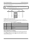
The supplemental grounding conductor shall be connected to the equipment using a number 8 ring terminal
and should be fastened to the grounding lug provided on the rear panel of the equipment. The ring terminal
should be installed using the appropriate crimping tool (AMP P/N 59250 T-EAD Crimping Tool or
equivalent.)
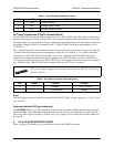
6. SUPPLYING POWER TO THE UNIT
The TRACER 5045 can operate from a supply between 21 and 60 VDC, with either polarity referenced to
ground. Power supplies should be able to provide up to 24 Watts at the selected voltage. A dual pin
terminal plug accepts power at the rear panel of the unit, providing a + and - polarity reference point.
Adapters for this plug are available (P/N 1175043L2) and are furnished with the unit and optional power
supply (P/N 1280650L1).
7. MOUNTING OPTIONS
Install the TRACER 5045 in a location that requires minimal antenna feedline length (the loss in this cable
directly affects overall system performance). The TRACER 5045 is designed to be mounted in a rack. If
multiple units are installed in one location, one half inch of spacing is recommended above and below the
unit.
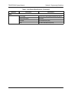
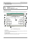
8. CONNECTING THE ETHERNET INTERFACES
The physical Ethernet interfaces are provided using four RJ-48C jacks. Ethernet cables are not supplied
with your shipment. Connect any standard Ethernet device to one of the switch ports located on the rear of
the unit.
The supplemental equipment grounding terminal is located on the rear panel of the
TRACER 5045.
• This unit shall be installed in accordance with Article 400 and 364.8 of the NEC NFPA
70 when installed outside of a Restricted Access Location (i.e., central office, behind a
locked door, service personnel only area).
• Power to the TRACER 5045 DC system must be from a reliably grounded
21-60 VDC source which is electrically isolated from the AC source.
• The branch circuit overcurrent protection shall be a fuse or circuit breaker rated
minimum 60 VDC, maximum 10A.
• A readily accessible disconnect device that is suitably approved and rated shall be
incorporated in the field wiring.