


TRACER 5045 System Manual Section 3 Engineering Guidelines
612805045L1-1A © 2003 ADTRAN, Inc. 31
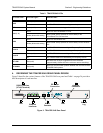
DC Power Connection (Plug-In Terminal Block)
The TRACER 5045 can operate from a supply between 21 and 60 VDC, with either polarity referenced to
ground, and consumes less than 23 Watts (W). Power supplies should be able to provide up to 24 W at the
selected voltage. Current required (in Amps) is determined by dividing the power consumed (in Watts) by
the applied voltage (in Volts). For example, at 48 V, TRACER 5045 would draw approximately 0.48 A
(23 W/48 V).
The + terminal of the DC power connection must be connected to the most positive voltage rail, while the
– terminal must be connected to the most negative voltage rail. For example, a +24 V source should be
delivered to the TRACER 5045 by connecting +24 V to the + terminal of the TRACER 5045 power
terminal block and ground (the most negative voltage) to the TRACER 5045 – terminal. Alternately, a
-48V supply should be delivered to the TRACER 5045 by connecting ground (the most positive voltage) to
the + terminal of the TRACER 5045 power terminal block and -48 V to the – terminal.
Fuse
The fuse holder, accessible from the rear panel of the TRACER 5045, accepts a generic 2 A, 250 V, 2-inch
slow-blo fuse.
Antenna Interface (N-Type connector)
The ANTENNA interface (N-Type connector) connects to the customer-supplied antenna using standard
antenna feedline cable. When determining the cable specifications for your application, refer to Section 2,
Microwave Path Engineering Basics (System Losses (L) on page 18) for a discussion on cable length and
loss factors.
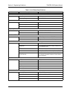
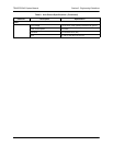
5. AT-A-GLANCE SPECIFICATIONS
Table 9 on page 32 contains a list of specifications for the TRACER 5045 system.
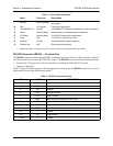
Table 7. Alarm Contact Connector Pinout
PIN NAME DESCRIPTION
1 COM Common Contact
2 NO Normally-Open Contact
3 NC Normally-Closed Contact
If the power supply voltages are incorrectly connected to the TRACER 5045 system,
the fuse will blow.
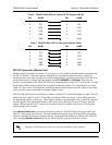
Table 8. DC Power Connector Example Pinout
PIN NAME + Voltage – Voltage
1 + + Voltage Ground (GND)
2 - Ground (GND) – Voltage