


xvi
Figures
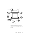
Figure 1-1: The panel PC in perspective...................................................3
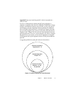
Figure 1-2: How to read the PPC-120/140 manual ...................................5
Figure 1-3: Dimensions of the PPC-120/140 ..........................................10
Figure 2-1: Front view of the panel PC ...................................................12
Figure 2-2: Left side view of the panel PC ..............................................13
Figure 2-3: Rear view of the panel PC ....................................................14
Figure 2-4: Tilted rear view of the panel PC............................................15
Figure 2-5: Connecting the power cord...................................................16
Figure 2-6: Connecting the keyboard and mouse ...................................17
Figure 3-1: Inserting and ejecting a floppy diskette .................................22
Figure 3-2: Inserting and ejecting a CD-ROM Disc .................................23
Figure 3-3: Inserting and ejecting a PCMCIA card ..................................24
Figure 3-4: Using the I/O interface
(upper level ports excluding COM ports) ............................25
Figure 3-5: Using the I/O interface (lower level ports and COM ports)....26
Figure 3-6: PCI/ISA bus expansion.........................................................28
Figure 4-1: Disassembling the rear panel of the panel PC ......................36
Figure 4-2: Installing the primary 2.5" HDD.............................................37
Figure 4-3: Installing the CPU .................................................................39
Figure 4-4: Installing the SDRAM ...........................................................40
Figure 4-5: Installing the FDD .................................................................41
Figure 4-6: Installing the CD-ROM drive .................................................42
Figure 5-1: Locating jumpers on the PPC-120/140 motherboard ............46
Figure 5-2: Locating connectors on the PPC-120/140 motherboard .......48
Figure 9-1: Setup program initial screen .................................................98
Figure 9-2: CMOS setup screen .............................................................99
Figure 9-3: BIOS features setup screen ............................................... 101
Figure 9-4: Chipset features setup screen ............................................ 104
Figure 9-5: Power management setup screen ......................................105
Figure 9-6: PNP/PCI configuration setup screen ..................................109
Figure 9-7: Load BIOS defaults screen................................................. 111
Figure 9-8: Integrated peripherals screen .............................................112
Figure 9-9: IDE HDD auto detecton screen ..........................................116
Figure 9-10: Save and exit setup screen ..............................................117