146
PPC-120/140 User’s Manual
If you want to completely disassemble the panel PC, follow the
step-by-step procedures below. Users should be aware that Advantech
Co., Ltd. takes no responsibility whatsoever for any problems or damage
caused by the user’s disassembly of the panel PC. Make sure the power
cord of the panel PC is unplugged before you start disassembly.
The following procedures do not include the detailed disassembly
procedures for the CPU, HDD, CD-ROM drive, FDD, and SRAM; all of
which can be found in Chapter 4.
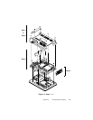
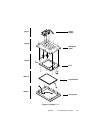
1. Unscrew the seven screws on the rear cover, and remove it. The
PCI/ISA expansion slot cover can be detached by removing the two
additional screws.
2. Remove the side panel by pushing it outward.
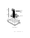
3. Unscrew the four screws that attach the CPU cover.
4. Detach the flat cable of the HDD, FDD and CD-ROM drive. Remove
the two screws on the PCI/ISA bus expansion card. Remove the ten
screws on the side rim of the shielding case. Carefully move the
shielding case to the right to bypass the eject buttons of the PCMCIA
slot, before removing the case from the machine. The electric fan and
power inlet can also be removed from the case by unscrewing the
screws.


